
Passive optical network monitoring method and passive optical network

a passive optical network and monitoring method technology, applied in the field of passive optical networks, can solve the problems of difficult separation, unfavorable chromatic dispersion change, and distortion of transmitted data, and achieve the effect of reducing the attenuation of round trip

Inactive Publication Date: 2009-11-17
RPX CORP
View PDF9 Cites 22 Cited by
  • Summary
  • Abstract
  • Description
  • Claims
  • Application Information

AI Technical Summary

Benefits of technology

The invention provides a method for monitoring a passive optical network by sending optical monitoring signals through each section of the network using different transceivers. The signals are sent at specific times and can be coordinated to create a measuring signal that is stronger and more accurate. This method allows for better monitoring of each individual fiber link branch of the network and can be easily adapted to existing networks. Additionally, the method can use pulsed signals and time scheduling to optimize the monitoring process. Overall, the invention improves the monitoring of passive optical networks.

Problems solved by technology

Most fiber link problems are related to increased losses and reflections that either prevent from error free detection of the data or that disturb the emitting loser, causing distortions of the transmitted data.
Problems due to changes of the chromatic dispersion are unlikely due to the low data rates considered in access.
It is difficult in a PON network to check the fiber link properties beyond a passive distribution node from the central office side because the responses, i.e. back scattered reflections, from all connected fiber link branches beyond the splitters are superimposed and a separation is not easily possible.
Therefore, the use of existing conventional CO-based OTDR techniques for optical performance monitoring like the single pulse method is not applicable to achieve unambiguous results in PON-type optical distribution networks.
Furthermore, optical time domain reflectometry in passive optical networks can suffer from the significant splitting losses which are reducing the achievable measurement precision and are increasing the necessary measurement time.
Especially PONs with distributed splitting location hinder reflectometric measurements of intermediate links, meaning fiber links between two splitters.
The basic problem to use OTDR technique in PON is the measuring at the distribution section, i.e. the fiber links after a splitter (distribution fibers), because of the attenuation of the forward signal, i.e. the exciting signal, as well as of the back scattered measuring signal.
This attenuation causes the power level of the back scattered parts of a measuring signal emitted from OLT side to be not high enough for the desirable precise and sensitive measuring.
The known monitoring approaches cause considerable technical effort and high costs.
The dedicated OTDR equipment is expensive and often has to be transported to the expected fault site on demand.
The extra coupling devices introduce permanent additional insertion loss in the data link.
No continuous monitoring is achievable.

Method used


Image

  • Passive optical network monitoring method and passive optical network
  • Passive optical network monitoring method and passive optical network

Examples


Embodiment Construction

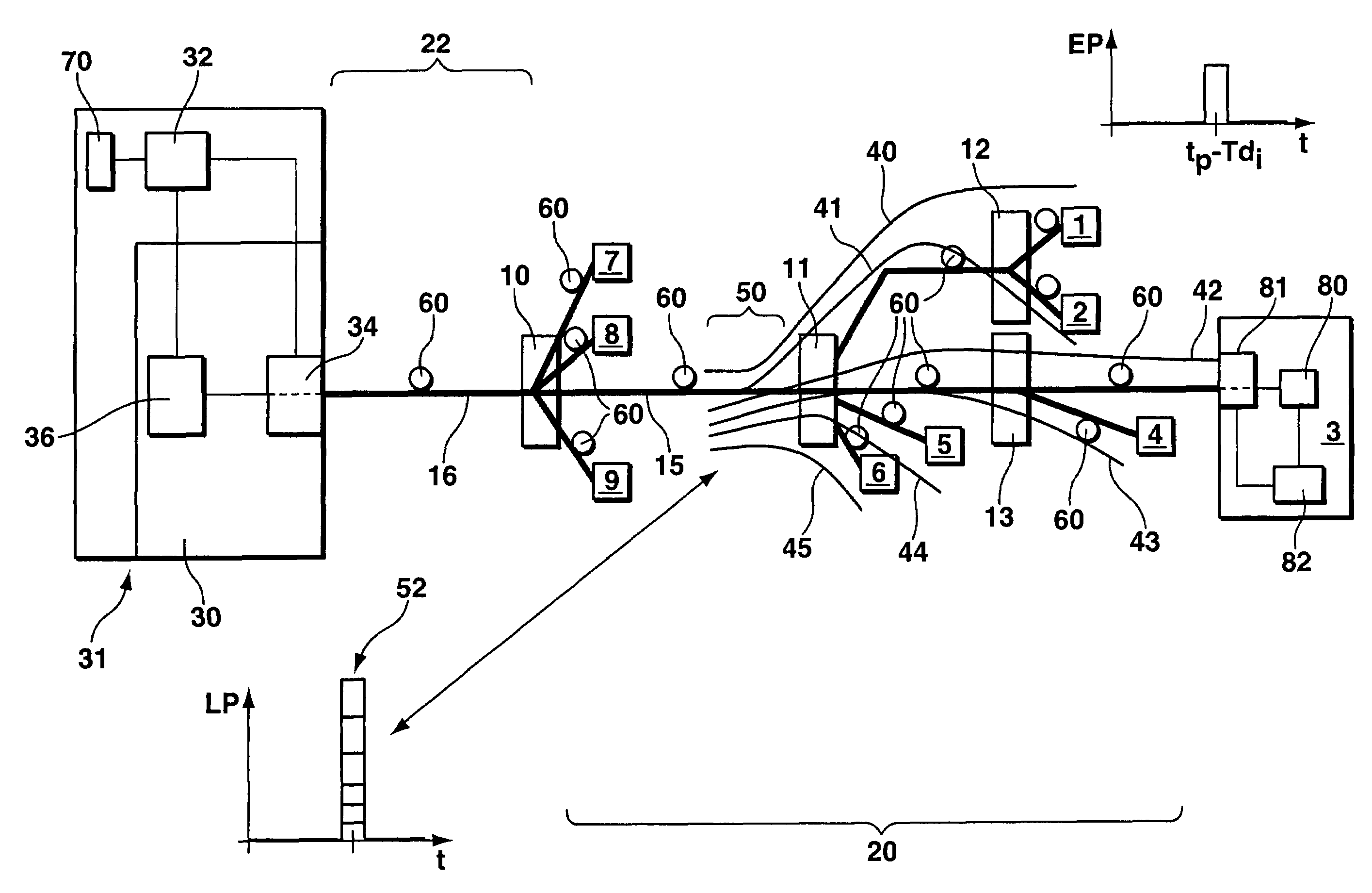
[0043]The Optical Distribution Network is shown schematically. The Optical Distribution Network is comprising four passive distribution nodes 10-13, e.g. optical splitters, and optical fiber links 15 of a distribution section 20 behind the first passive distribution node 10, meaning the range between the first distribution node 10 and fiber terminating Optical Network Units 1-9 (subscriber stations), and an optical fiber link 16 of a feeder section 22 up to said first passive distribution node 10. The passive Optical Distribution Network is comprising nine Optical Network Units 1-9 and an Optical Line Terminal 30 as transceiver devices. Eight of the ONUs are only shown as single boxes for illustration purposes. The Optical Line Terminal 30 is part of a central station 31 according to the invention. The central station 31 of the Passive Optical Network is comprising time scheduling means 32 and sending means 34, which are identical with sending means of the OLT 30. The time schedulin...


PUM


Abstract

This invention relates to a method for monitoring at least one section (50) of an optical fiber link (15,16), preferably a distribution section behind a passive distribution node (10-13), of a passive Optical Network, and a passive Optical Network being designed to perform the steps of the method. The method is comprising the steps of:—sending a first optical monitoring signal (40) through said section at a first signal sending time by sending means (81,34) of a first transceiver device (30,1-9) of the passive Optical Network,—sending at least a second optical monitoring signal (41-45) through said section at a second signal sending time by sending means (81,34) of a second transceiver device (30,1-9) of the passive Optical Network, wherein the sending times of said optical monitoring signals (40-45), preferably Optical Time Domain Reflectometry Signals, are coordinated in such a way that the optical monitoring signals (40-45) are superimposed while travelling through said section, building a measuring signal (52), and—detecting and analysing characteristics of at least parts of said measuring signal (52) preferably by at least one of the optical monitoring signal sending transceiver devices (1-9).

Description

[0001]The invention is based on a priority application EP 04293072.7 which is hereby incorporated by reference.FIELD OF THE INVENTION[0002]This invention relates to a passive Optical Network (PON), in particular an Optical Distribution Network (ODN), monitoring method and a passive Optical Network, being designed to carry out the steps of the monitoring method. The passive Optical Network is comprising at least an optical fiber link connecting two transceiver devices, one being an Optical Line Terminal (OLT) and one being a fiber termination, e.g. an end user (Subscriber) Optical Network Unit (ONU). An Optical Distribution Network is comprising at least one passive distribution node and optical fiber links of a distribution section behind said passive distribution node (splitter) and at least one optical fiber link of a feeder section up to said passive distribution node. In an Optical Distribution Network Optical Network Units are connected to the optical fiber link of a drop secti...

Claims


Application Information

Patent Timeline
Patent Type & Authority Patents(United States)
IPC IPC(8): H04B10/08H04J14/00H04B10/071
CPCH04B10/071
Inventor KRIMMEL, HEINZ-GEORG
Owner RPX CORP
Learn More