
Developing device and image forming device

a technology of developing devices and image forming devices, which is applied in the direction of instruments, electrographic process devices, optics, etc., can solve the problems of unstable image quality and hinder the smooth circulation of developers, and achieve the effect of stabilizing the circulation of developers

Inactive Publication Date: 2009-11-17
SHARP KK
View PDF24 Cites 10 Cited by
  • Summary
  • Abstract
  • Description
  • Claims
  • Application Information

AI Technical Summary

Benefits of technology

The present invention provides a developing device for an image forming device that optimizes the arrangement of a reflux plate to stabilize the reflux of developer and enhance the circulation of developer. The device includes a stirring roller with stirring blades for stirring the developer, a developing roller for transferring the developer to an electrostatic latent image, and a control member for controlling the amount of developer transferred. The reflux plate is designed to prevent deposition of developer and improve image quality. The device also uses a small-grain diameter developer for better image quality. The one end portion of the reflux plate is positioned remote from the stirring roller to prevent deposition of developer. The invention provides a developing device that optimizes the arrangement of a reflux plate to stabilize the reflux of developer and enhance the circulation of developer.

Problems solved by technology

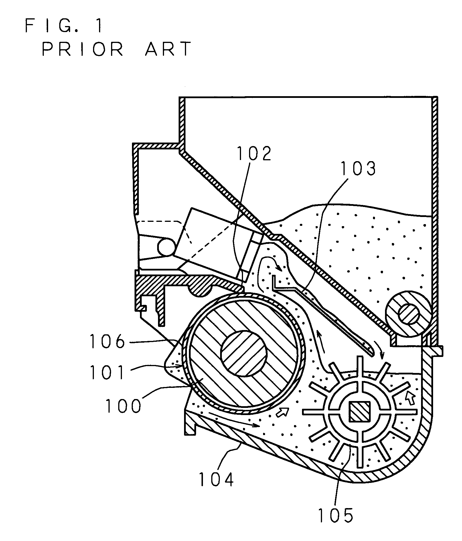
Nevertheless, for example, when the developer deposits on the reflux plate 103 so that the reflux of the developer is blocked, a problem arises that smooth circulation of the developer is prevented.
When smooth circulation of the developer is prevented, adverse influences are caused such as unstable image quality.

Method used


Image

  • Developing device and image forming device
  • Developing device and image forming device
  • Developing device and image forming device

Examples


Embodiment Construction

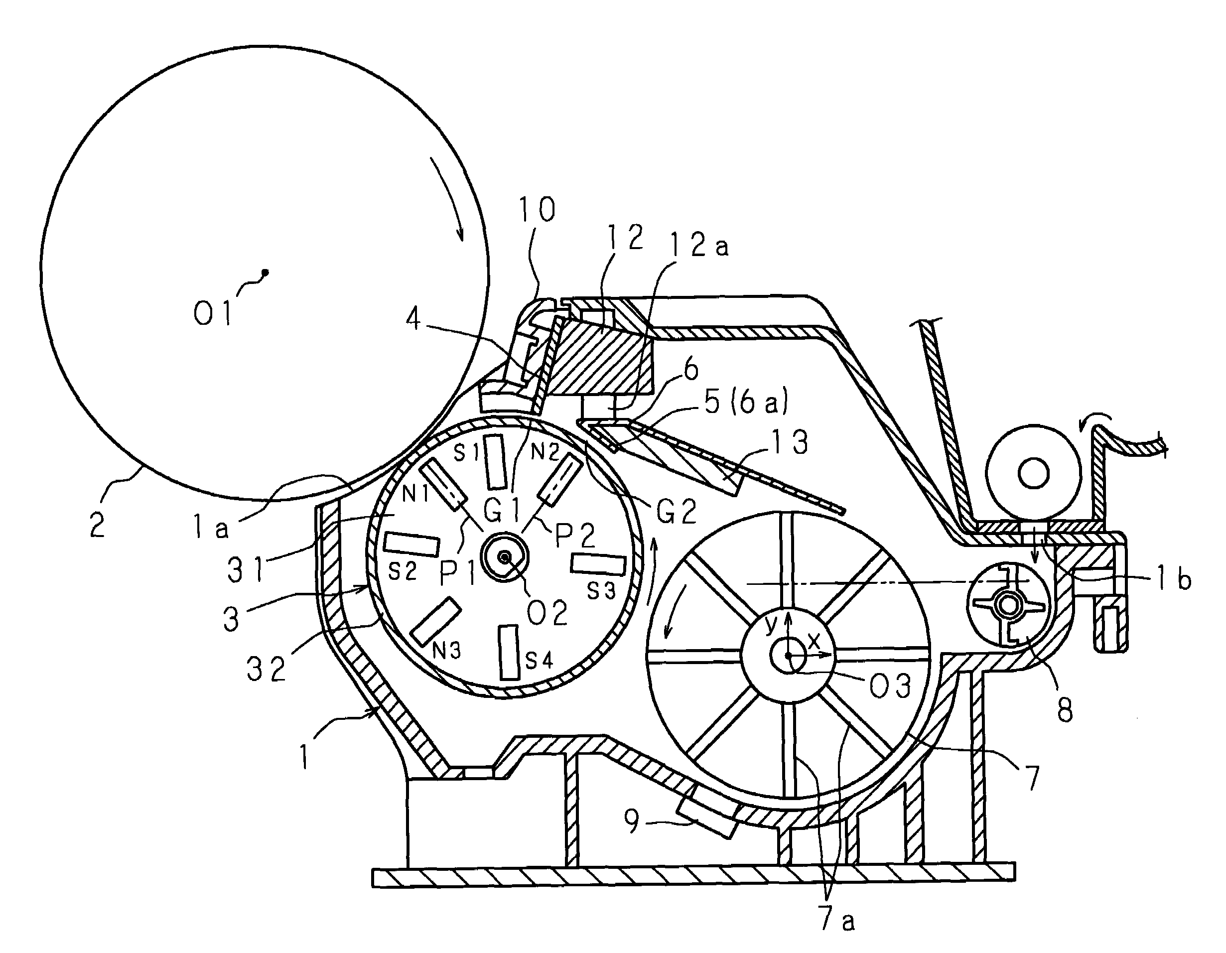
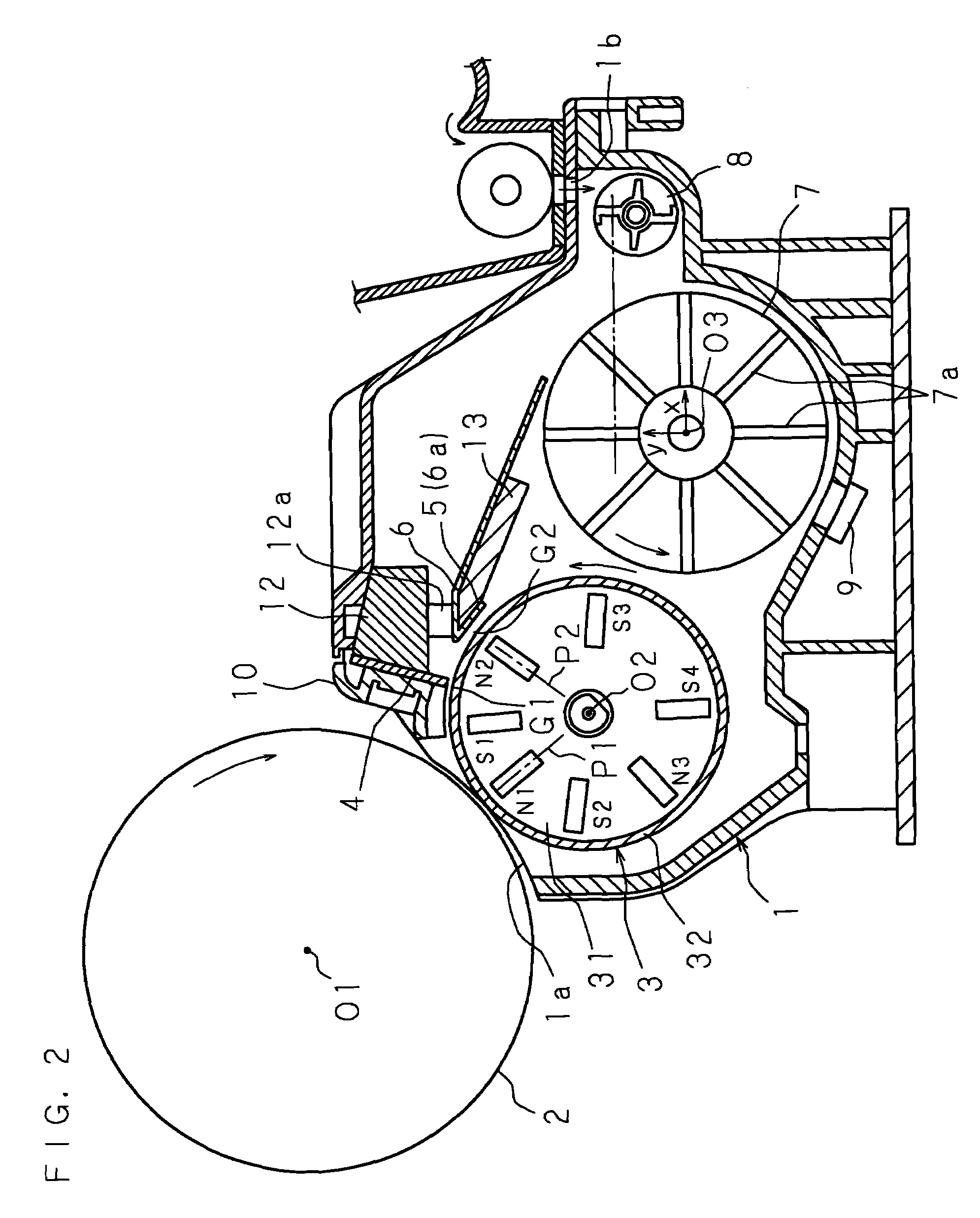
[0050]One or more aspects are described below in detail with reference to the drawings showing embodiments. FIG. 2 is a sectional view showing the configuration of a developing device according to a non-limiting embodiment. The developing device comprises: a case 1 for storing binary developer; a stirring roller 7 having stirring blades 7a and stirring the developer inside the case 1; a developing roller 3 for transferring the developer to an electrostatic latent image carried on a photosensitive drum 2 and for developing the electrostatic latent image; a control member 4 controlling the transferring amount of the developer to the electrostatic latent image at midway to the developing roller 3; a scraping member 5 facing the developing roller 3 with spacing of a second gap G2 larger than a first gap G1 formed between the developing roller 3 and the control member 4, controlling the layer thickness of the developer transferred to the first gap G1, and then scraping the developer; and...


PUM


Abstract

A developing device comprises a stirring roller 7 having stirring blades 7a for stirring a developer, a developing roller 3 for transferring the developer to an electrostatic latent image, a control member 4 for controlling the amount of developer transferred from the developing roller 3 to the electrostatic latent image, a reflux plate 6 by which the excess developer resulting from control by the control member 4 is flowed back to the stirring roller 7, one end portion of the reflux plate 6 being disposed in the vicinity of the outer periphery of the stirring roller 7, part of the developer stirred by the stirring roller 7 flying toward the reflux plate 6, wherein said one end portion of the reflux plate 6 is disposed at a position remote from the stirring roller 7 over a distance greater then the maximum fly distance of the developer provided by rotation of the stirring roller 7.

Description

CROSS-REFERENCE TO RELATED APPLICATIONS[0001]This application is the national phase under 35 U.S.C. §371 of PCT International Application No. PCT / JP04 / 12994 which has an International filing date of Sep. 7, 2004 and designated the United States of America.BACKGROUND OF THE INVENTION[0002]1. Field of the Invention[0003]The described technology relates to a developing device used in an image forming device such as a copying machine, a printer, and a facsimile machine employing an electro-photographic system, and relates to an image forming device.[0004]2. Description of Related Art[0005]FIG. 1 is a sectional view showing the configuration of a conventional developing device. The developing device used in an image forming device such as a copying machine employing an electro-photographic system comprises: a case 104 for storing binary developer; a stirring roller 105 for stirring the developer inside the case 104; a developing roller 101 for transferring the developer to an electrostat...

Claims


Application Information

Patent Timeline
Patent Type & Authority Patents(United States)
IPC IPC(8): G03G15/09G03G15/08
CPCG03G15/081G03G2215/0609
Inventor ONDA, HIROSHINISHINO, TOSHIOTOMITA, SYOHJIWAKABAYASHI, TAKESHIISHII, HIROSHI
Owner SHARP KK
Learn More