

Pump
- Summary
- Abstract
- Description
- Claims
- Application Information
AI Technical Summary
Benefits of technology
Problems solved by technology
Method used
Image

Examples
Embodiment Construction
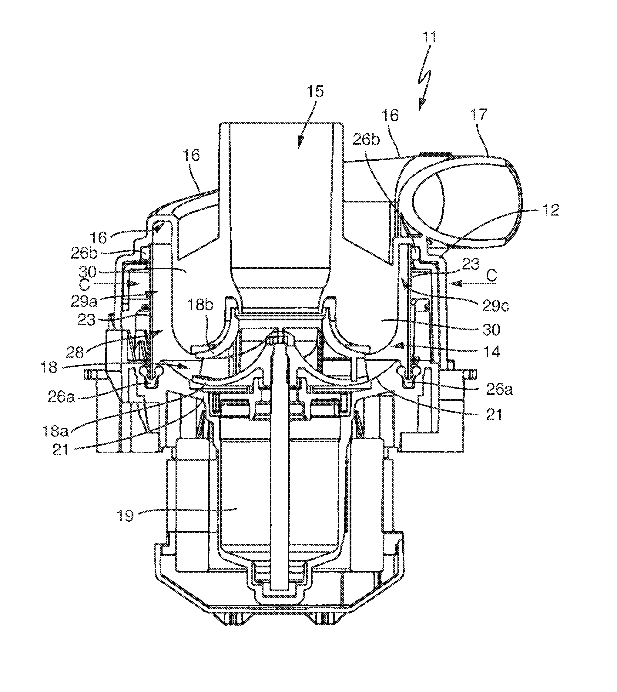
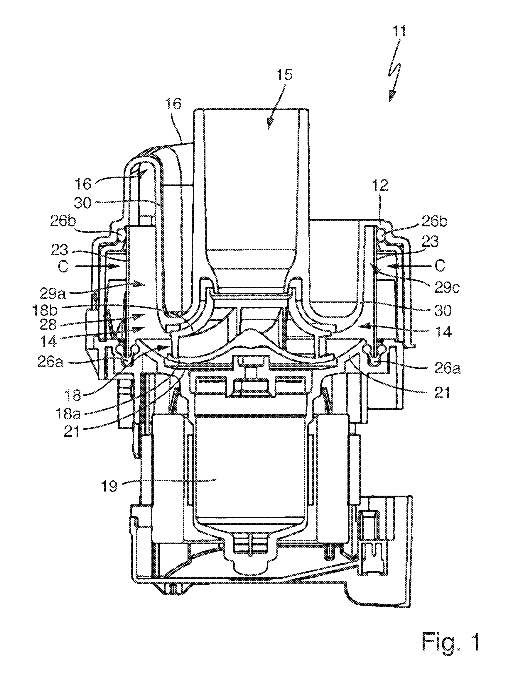
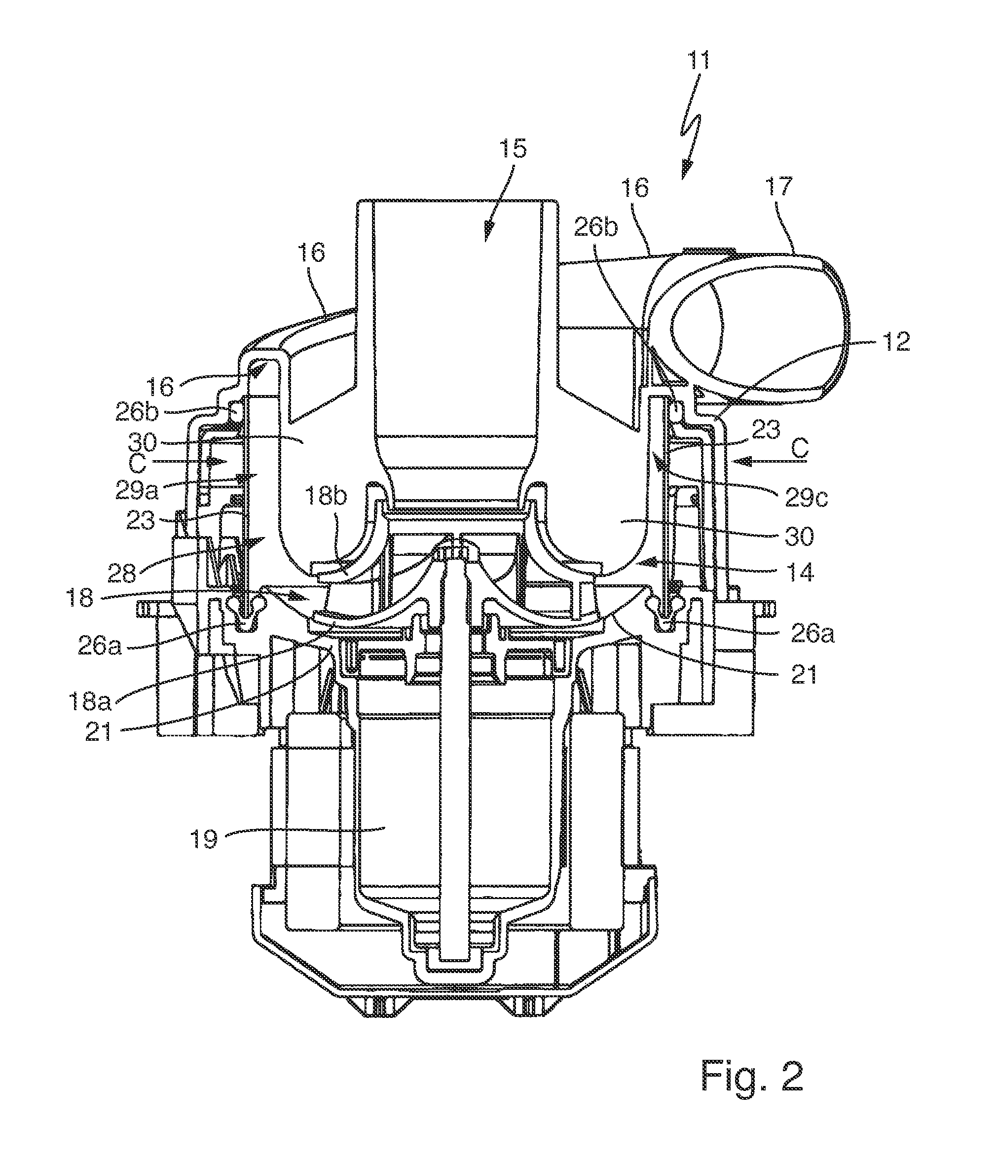
[0025]In FIG. 1 a pump 11 with a pump housing 12 is shown as generally known from the aforementioned prior art. The pump housing 12 comprises a pump chamber 14 and a central axial suction pipe 15 leads into said chamber and an outlet 16 leads out of said chamber in the tangential direction. The suction pipe 15 leads exactly towards a centrally arranged impeller 18 with a lower cover plate 18a and an upper cover plate 18b. The impeller 18 is driven by a pump motor 19 and extends above a pump chamber bottom 21 having a step-like, central depression adapted to the lower cover plate 18a.
[0026]The radially exterior wall of the pump chamber 14 is formed by a tubular heating device 23 as for example known from U.S. Pat. No. 8,245,718 B, namely as a metallic tube having a constant diameter with the ends cut off in a straight manner. On the exterior side of the tube, heating elements not shown are provided for the heating device 23, advantageously thick-film heating elements.
[0027]The heati...
PUM
 Abstract
Description
Claims
Application Information