Exhaust gas recirculation system for internal combustion engine

A technology of recirculation system and internal combustion engine, applied in exhaust gas recirculation, internal combustion piston engine, charging system, etc., can solve problems such as real-time control of EGR under adverse transient conditions, limited working range of exhaust gas circulation, and EGR cannot be circulated at a high proportion. , to solve the problem of supercharger delay, which is conducive to fast response and fast response of exhaust gas circulation

Inactive Publication Date: 2011-01-26
HUNAN UNIV
View PDF6 Cites 6 Cited by
  • Summary
  • Abstract
  • Description
  • Claims
  • Application Information

AI Technical Summary

Problems solved by technology

However, the temperature of the recirculated exhaust gas using this method is too high, resulting in a high heat load of the EGR intercooler. The temperature of the recirculated exhaust gas after intercooling is still higher than the temperature of the cooling water. The temperature of the charge is not conducive to reducing the combustion temperature; secondly, this method has poor response characteristics under variable working conditions, which is not conducive to the real-time control of EGR in transient working conditions; thirdly, this method reduces the high-pressure and high-energy exhaust gas passing through the turbine, which is not conducive to Conducive to boost pressure increase
[0009] The other is to introduce the exhaust gas after the turbine into the front of the compressor, which is called a low-pressure exhaust gas recirculation system, which can effectively reduce nitrogen oxides, and the recirculation waste temperature is low, which is conducive to reducing the combustion temperature in the cylinder, but the exhaust gas circulation is limited. , EGR cannot be circulated at a higher ratio, and the recirculated exhaust gas using this method has poorer response characteristics under changing operating conditions, which will cause a large difference between the target control EGR amount and the actual EGR amount entering the cylinder, resulting in in-cylinder combustion source emission difference

Method used


Image

  • Exhaust gas recirculation system for internal combustion engine
  • Exhaust gas recirculation system for internal combustion engine
  • Exhaust gas recirculation system for internal combustion engine

Examples


Embodiment Construction

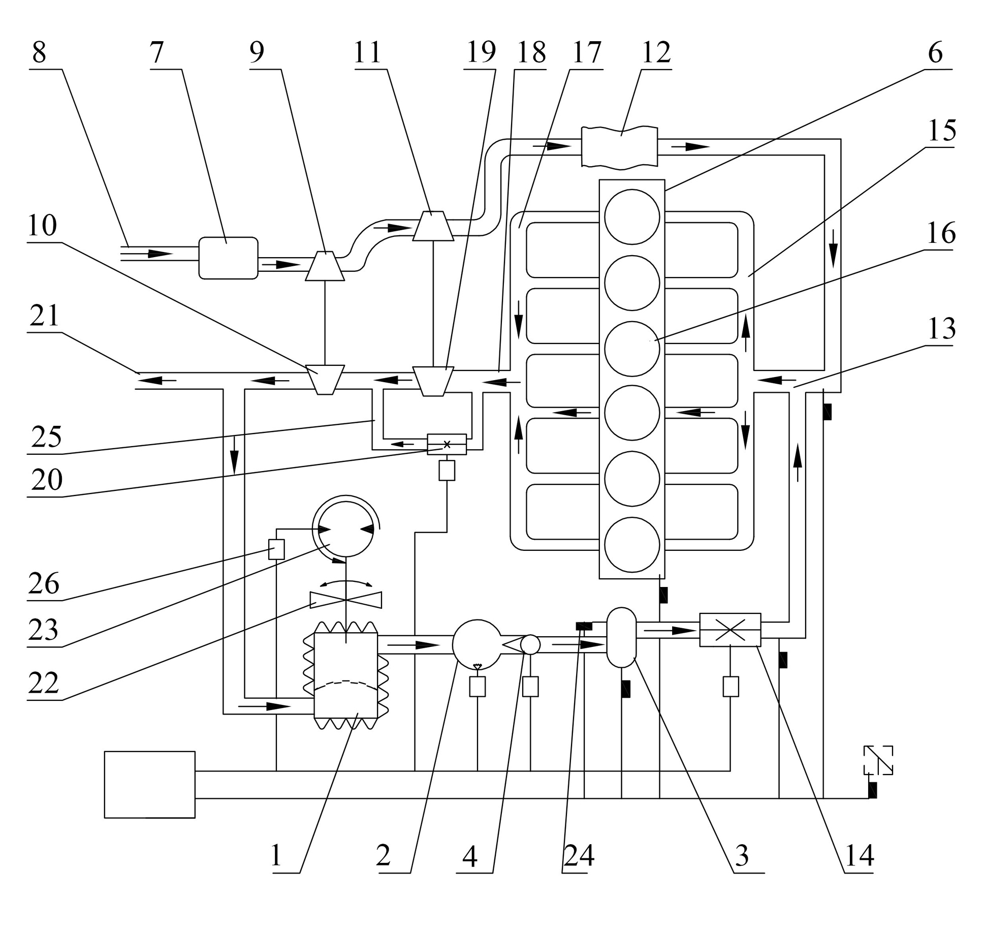
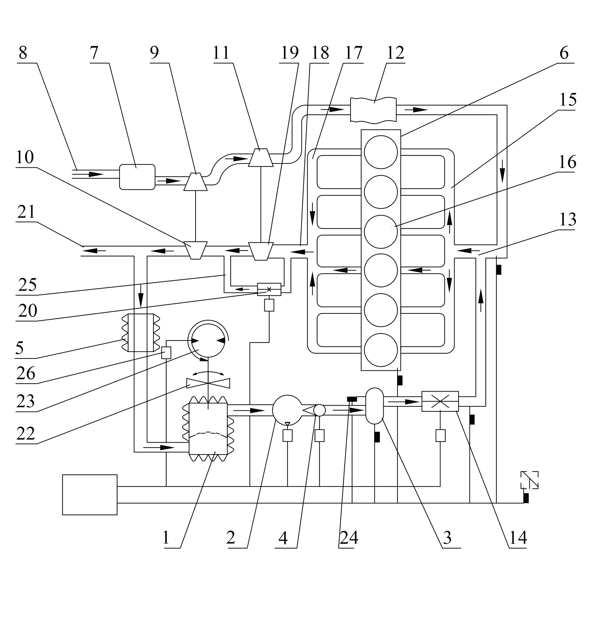
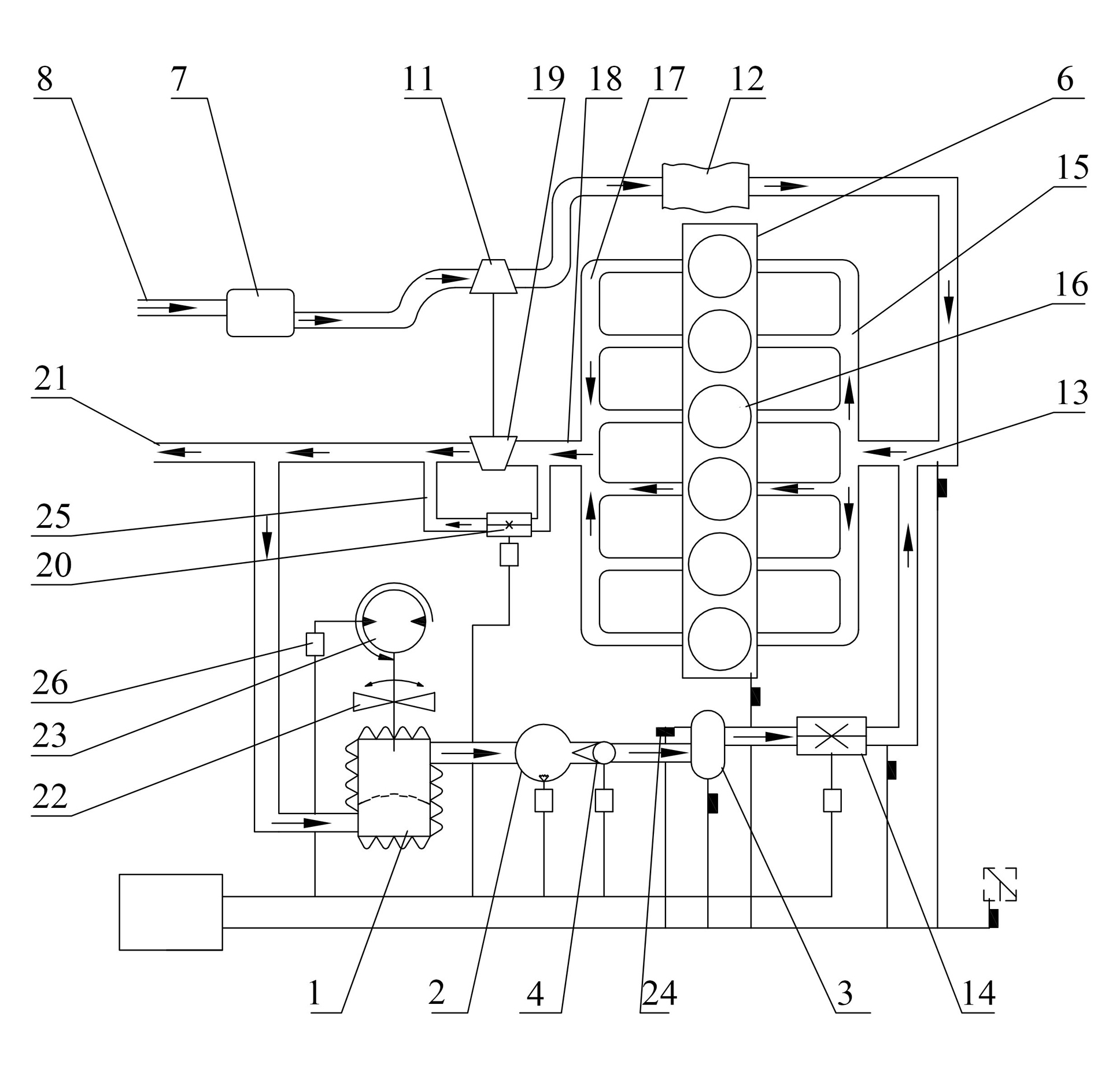
[0029] The present invention will be further described in detail below in conjunction with the accompanying drawings and specific embodiments.

[0030] Such as figure 1 As shown, it is a specific application example 1, the present invention is applied to a two-stage supercharged internal combustion engine. The internal combustion engine 6 takes a diesel engine as an example, and the working process of the diesel engine is divided into four strokes, which are respectively air intake, compression, work, and exhaust. The purpose of the exhaust gas recirculation (EGR) of the present invention is to reduce the combustion temperature in the cylinder (lower than 2000K), suppress the formation of NOx, and reduce the emission of pollutants. In this example, the EGR circulation mode belongs to the low-pressure exhaust gas recirculation system.

[0031] The exhaust gas recirculation system used for internal combustion engines of the present invention comprises a cooling assembly, a com...


PUM


Abstract

The invention discloses an exhaust gas recirculation system for an internal combustion engine. The exhaust gas recirculation system comprises a cooling component, a gas compressor and a gas storage tank which are connected in turn; a gas inlet end of the cooling component is communicated with an exhaust pipe of the internal combustion engine; and a gas outlet end of the gas storage tank is communicated with a gas inlet of the internal combustion engine. The exhaust gas recirculation system has the advantages of simple and compact structure, low cost, stable and reliable work, quick exhaust gas recirculation response, capability of effectively reducing harmful emissions of the internal combustion engine, accurate control on recirculation exhaust gas amount and the like.

Description

technical field [0001] The invention mainly relates to the field of internal combustion engines, in particular to an exhaust gas recirculation system for internal combustion engines. Background technique [0002] The internal combustion engine has the characteristics of small size, small mass, easy to move, high thermal efficiency, and good starting performance. It has been widely used in production and life, and has become one of its main power sources. However, the exhaust gas emitted by internal combustion engines has a high content of harmful gases, which seriously pollutes the atmospheric environment and affects human health. Therefore, in order to curb atmospheric environmental pollution, governments of various countries have promulgated increasingly stringent emission control regulations. [0003] Exhaust Gas Recirculation (Exhaust Gas Recirculation), referred to as EGR, is to send part of the exhaust gas generated by the internal combustion engine back to the cylind...

Claims


Application Information

Patent Timeline
IPC IPC(8): F02M25/07F02M26/22F02M26/31
CPCY02T10/121Y02T10/12
Inventor 刘敬平杨汉乾杨靖付建勤王树青王勇夏孝朗赵智超
Owner HUNAN UNIV
Why Eureka
Try Eureka