
Low pressure EGR system

A low-pressure, cooler technology, applied in the charging system, adding non-fuel substances to the fuel, internal combustion piston engines, etc., can solve the problems of heavy burden on the cooling system, insufficient cooling effect, and poor cooling effect of the secondary cooler, etc. Achieve the effect of improving cooling effect and high EGR rate

Inactive Publication Date: 2011-05-11
CHERY AUTOMOBILE CO LTD
View PDF7 Cites 2 Cited by
  • Summary
  • Abstract
  • Description
  • Claims
  • Application Information

AI Technical Summary

Problems solved by technology

[0005] The purpose of the present invention is to provide a low-pressure EGR system with two-stage coolers cooled by air-conditioning refrigerant, which overcomes the problem of excessive burden on the cooling system of single-stage coolers in the prior art, and solves the problem of conventional two-stage cooler cooling. The problem of poor effect; thereby providing a low-pressure EGR system with a two-stage cooler cooled by air-conditioning refrigerant to improve engine performance and emissions
[0006] Another object of the present invention is to provide an exhaust gas cooling system in a low-pressure EGR system, which uses the compressed refrigerant of the vehicle air-conditioning system to overcome the cooling effect of conventional single-stage coolers in the prior art that only use the engine cooling circulation system for cooling Insufficient problem

Method used


Image

  • Low pressure EGR system
  • Low pressure EGR system

Examples


Embodiment Construction

[0021] The present invention will be described in detail below according to the accompanying drawings, which is a preferred embodiment among various implementations of the present invention.

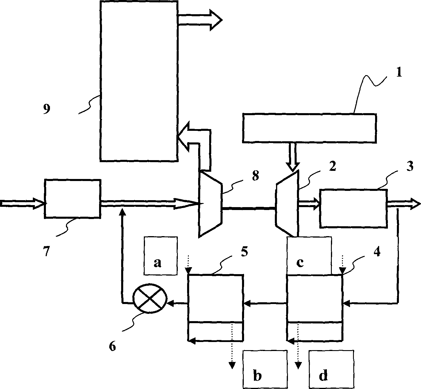
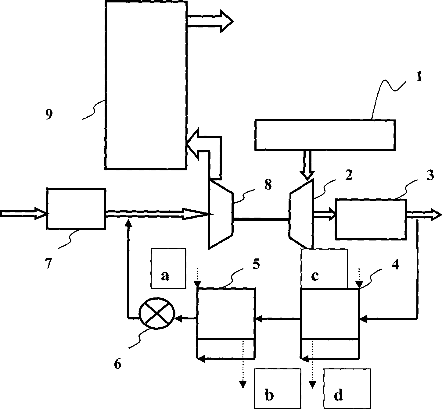
[0022] Such as figure 1 Shown is a schematic diagram of a low-pressure EGR system with an air-conditioning system refrigerant secondary cooling exhaust gas. The exhaust gas flows into the turbocharger turbine 2 through the exhaust manifold 1, then flows out from the particle trap 3, and is discharged into the outside world through the vehicle exhaust pipe and the muffler system. EGR exhaust gas is taken after the particle trap 3, passes through the EGR primary cooler 4 and the EGR secondary cooler 5, the flow is controlled by the EGR control valve 6, and then flows into the engine intake system from the air filter 7 with fresh air Mixed, after being pressurized by the supercharger compressor 8, it flows into the intercooler 9, and then flows into the combustion chamber through the engin...


PUM


Abstract

The invention relates to a low-pressure EGR system; the waste gas is extracted from the backside of the particle trap by the EGR system and is forced to be cooled via the first stage cooler and the second stage cooler; the cooled waste gas is controlled and adjusted on the flow rate by the EGR valve to be mixed with the compression air discharged from the air filter in front of the compressor of the supercharger; then the mixed gas is imported into the intercooler and flows into the engine combustion chamber for combustion; wherein, a cooler shares part of the refrigerant of the air-conditioner system of the automobile to cool the EGR waste gas. Under the situation that no extra cooler is added, the cooling effect on the waste gas is improved greatly; the homogeneous intake is provided for the engine, so as to obtain higher EGR rate.

Description

technical field [0001] The present invention relates to a low-pressure EGR system in the field of engine low-pressure exhaust gas recirculation (EGR), in particular to an exhaust gas cooling system in the low-pressure EGR system. Background technique [0002] The exhaust gas recirculation (EGR) system of the internal combustion engine is a very important device of the engine. A part of the exhaust gas is drawn from the exhaust pipe, enters the intake manifold through the exhaust gas recirculation system, and is distributed to each cylinder for combustion, which effectively reduces the engine exhaust. Emissions of nitrogen oxides in air pollutants. Exhaust gas recirculation systems are commonly used in automobile engines to reduce emissions. [0003] At present, high-pressure EGR is mainly used in the market. Compared with high-pressure EGR, low-pressure EGR has some other advantages. At the air place, the total pressure of the exhaust gas is higher than the pressure of the...

Claims


Application Information

Patent Timeline
Patent Type & Authority Patents(China)
IPC IPC(8): F02M25/07F02M26/24F02M26/25
CPCY02T10/12
Inventor 王钦庆
Owner CHERY AUTOMOBILE CO LTD
Learn More