
Combustion stability enhancement via internal EGR control

a technology of combustion stability and internal egr control, which is applied in the direction of electric ignition installation, machines/engines, mechanical equipment, etc., can solve the problems of increasing the nitrogen-oxide (nosub>x/sub>) emissions of the engine, accelerating the ageing of materials, and reducing combustion and exhaust temperatures. , to achieve the effect of reducing the oxygen content of the engine, increasing the combustion and exhaust temperature, and increasing the emission of nitrogen-oxide (nox

Active Publication Date: 2014-05-27
FORD GLOBAL TECH LLC
View PDF14 Cites 2 Cited by
  • Summary
  • Abstract
  • Description
  • Claims
  • Application Information

AI Technical Summary

Benefits of technology

[0003]A boosted engine may exhibit higher combustion and exhaust temperatures than a naturally aspirated engine of similar output power. Such higher temperatures may cause increased nitrogen-oxide (NOx) emissions from the engine and may accelerate materials ageing, including turbocharger and exhaust-aftertreatment catalyst ageing. Exhaust-gas recirculation (EGR) is one approach for combating these effects. EGR works by diluting the intake air charge with exhaust gas, thereby reducing its oxygen content. When diluted air is used in place of ordinary air to support combustion in the engine, lower combustion and exhaust temperatures result.
[0004]EGR can also improve fuel economy in gasoline engines. At medium and high loads, fuel economy is improved due to knock mitigation, allowing for more efficient combustion phasing, reduced heat loss to the engine coolant, and lower exhaust temperatures—which in turn reduce the need for enrichment to cool the exhaust components. At low loads, EGR provides an additional benefit of reducing throttling losses.
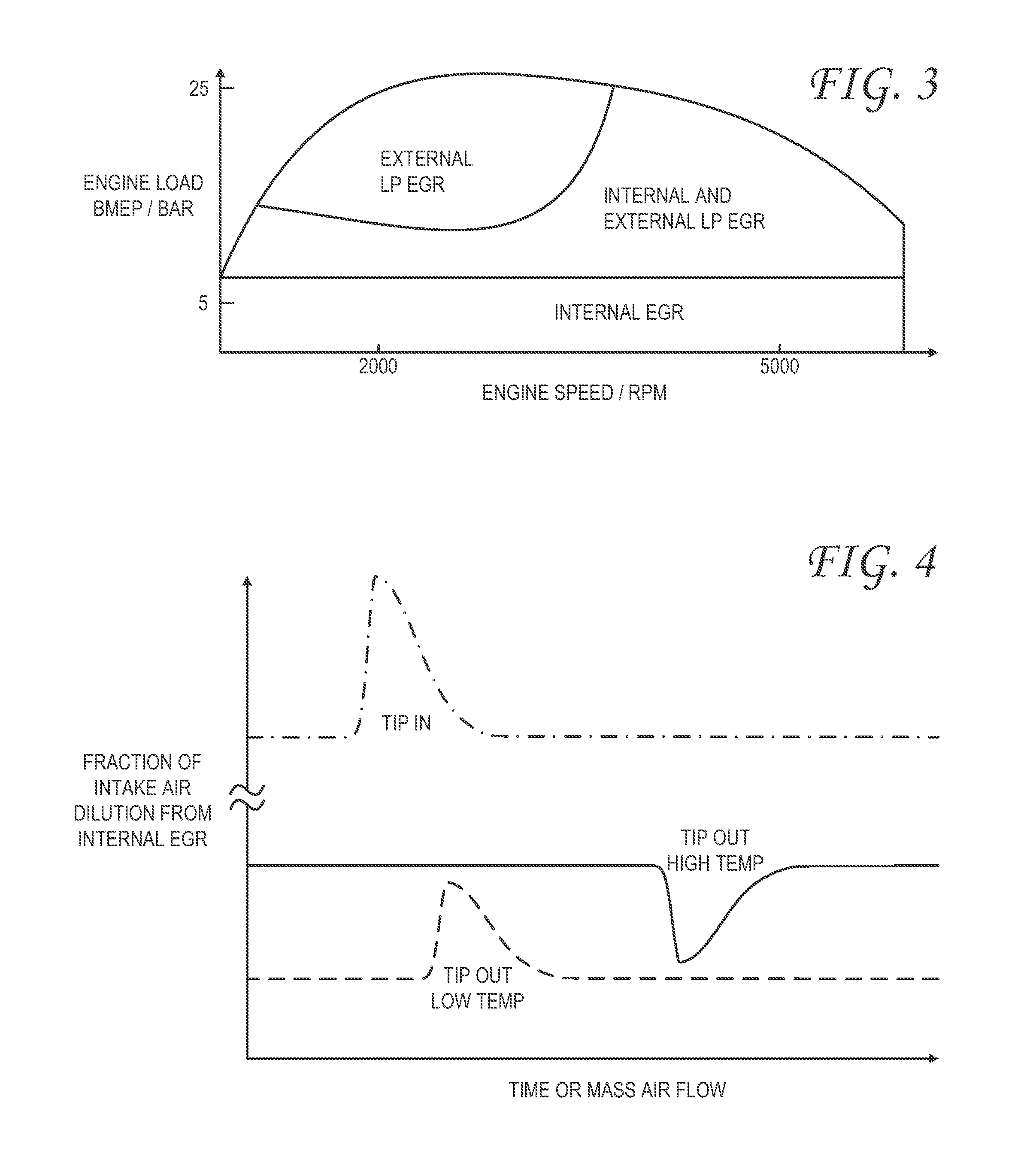
[0010]Therefore, one embodiment provides a method for controlling combustion in a cylinder of a turbocharged engine in which intake air is reserved upstream of the cylinder. The method comprises decreasing an internal EGR rate in the cylinder during a tip-out condition if the temperature of the intake air is above a threshold, and increasing the internal EGR rate in the cylinder during a tip-out condition if the temperature of the intake air is below the threshold. By applying divergent strategies to enhance combustion stability during tip out, depending on the intake-air temperature, various benefits are realized. Such benefits may include extending the steady-state operating range over which cooled LP EGR may be used, while protecting combustion stability during transients.

Problems solved by technology

Such higher temperatures may cause increased nitrogen-oxide (NOx) emissions from the engine and may accelerate materials ageing, including turbocharger and exhaust-aftertreatment catalyst ageing.
When diluted air is used in place of ordinary air to support combustion in the engine, lower combustion and exhaust temperatures result.
Moreover, each strategy presents its own control-system challenges.
For example, HP EGR is most effective at low loads, where intake vacuum provides ample flow potential; at higher loads, the desired EGR flow rate may be unattainable due to reduced flow potential.
Intrinsically dependent on turbocharger waste gate and throttle conditions, HP EGR may require a complex flow-control strategy.
Further, HP EGR may suffer from poor EGR / intake-air mixing and may require a high rate of active cooling due the short length between the HP EGR take-off point and the intake runners of the engine.
However, LP EGR may respond sluggishly to changing engine load, engine speed, or intake air flow.
In gasoline engines especially, such unsatisfactory transient response may result in combustion instability during tip-out conditions, when fresh air is needed to sustain combustion but EGR-diluted air is present upstream of the throttle valve.
Moreover, a significant lag in EGR availability can occur during tip-in conditions, as the amount of EGR accumulated in the intake manifold may not be sufficient to provide the desired combustion and / or emissions-control performance.
However, this reference does not contemplate the full range of control options that are possible when fast-responding internal EGR is coordinated with slower-responding external LP EGR.

Method used


Image

  • Combustion stability enhancement via internal EGR control
  • Combustion stability enhancement via internal EGR control
  • Combustion stability enhancement via internal EGR control

Examples


Embodiment Construction

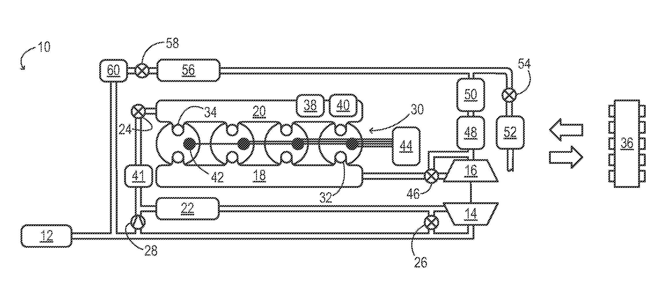
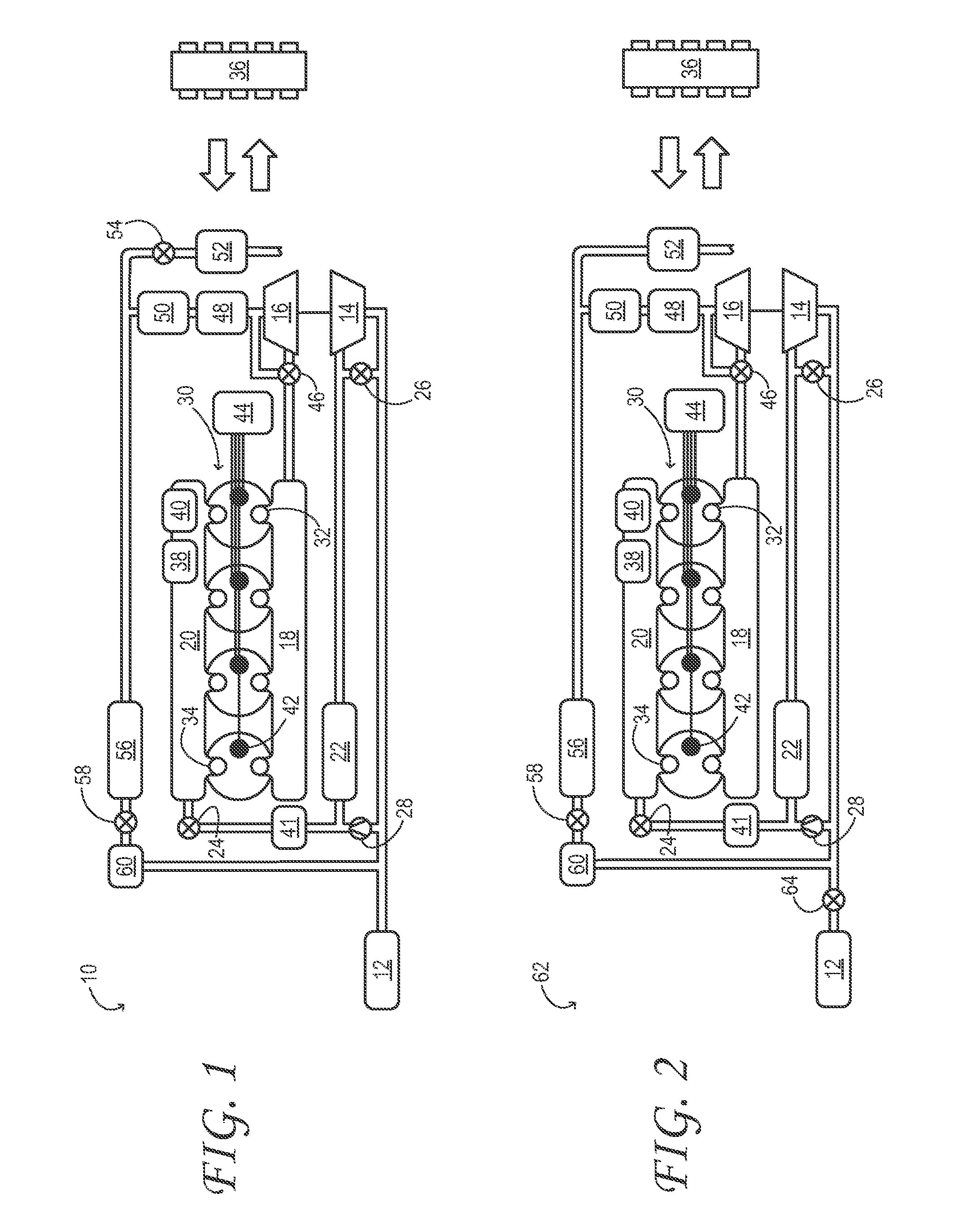
[0018]Aspects of this disclosure will now be described by example and with reference to the illustrated embodiments listed above. Components, process steps, and other elements that may be substantially the same in one or more embodiments are identified coordinately and are described with minimal repetition. It will be noted, however, that elements identified coordinately may also differ to some degree. It will be further noted that the drawing figures included in this disclosure are schematic and generally not drawn to scale. Rather, the various drawing scales, aspect ratios, and numbers of components shown in the figures may be purposely distorted to make certain features or relationships easier to see.

[0019]FIG. 1 schematically shows aspects of an example engine system 10 in one embodiment. In engine system 10, fresh air is inducted into air cleaner 12 and flows to compressor 14. The compressor may be any suitable intake-air compressor—a motor-driven or driveshaft driven superchar...


PUM


Abstract

A method for controlling combustion in a cylinder of a turbocharged engine in which intake air is reserved upstream of the cylinder. The method comprises decreasing an internal EGR rate in the cylinder during a tip-out condition if the temperature of the intake air is above a threshold, and increasing the internal EGR rate in the cylinder during a tip-out condition if the temperature of the intake air is below the threshold.

Description

CROSS REFERENCE TO RELATED APPLICATIONS[0001]This application is a continuation-in-part of U.S. patent application Ser. No. 12 / 753,716, filed Apr. 2, 2010 and entitled INTERNAL AND EXTERNAL LP EGR FOR BOOSTED ENGINES, the entirety of which is hereby incorporated by reference herein for all purposes.TECHNICAL FIELD[0002]This application relates to the field of motor-vehicle engineering, and more particularly, to air induction and exhaust-gas recirculation in motor vehicle engine systems.BACKGROUND AND SUMMARY[0003]A boosted engine may exhibit higher combustion and exhaust temperatures than a naturally aspirated engine of similar output power. Such higher temperatures may cause increased nitrogen-oxide (NOx) emissions from the engine and may accelerate materials ageing, including turbocharger and exhaust-aftertreatment catalyst ageing. Exhaust-gas recirculation (EGR) is one approach for combating these effects. EGR works by diluting the intake air charge with exhaust gas, thereby redu...

Claims


Application Information

Patent Timeline
Patent Type & Authority Patents(United States)
IPC IPC(8): F02M25/07F02B37/12
CPCF02B29/0406F02M25/0709Y02T10/146F02M25/0727F01N3/2066Y02T10/24F02M25/0718Y02T10/144F02B37/18Y02T10/121F02M26/06F02M26/15F02M26/23Y02T10/12
Inventor SURNILLA, GOPICHANDRASHELBY, MICHAEL HOWARDULREY, JOSEPH NORMANSTYLES, DANIEL JOSEPHHOUSE, CHRISTOPHERBOYER, BRAD ALANHILDITCH, JAMES
Owner FORD GLOBAL TECH LLC
Learn More