Engine device

a technology of engine and cylinder, applied in the direction of electrical control, propulsion-based emission reduction, motor-driven power plants, etc., can solve the problems of environmental protection, achieve the effects of preventing excessive in-cylinder pressure and abnormal combustion, avoiding excessive supply of fuel, and stable operation

Active Publication Date: 2020-06-23
YANMAR POWER TECHNOLOGY CO LTD
View PDF42 Cites 0 Cited by
  • Summary
  • Abstract
  • Description
  • Claims
  • Application Information

AI Technical Summary

Benefits of technology

[0020]In the present invention, the start of supplying the liquid fuel (start of operation in the diesel mode) is delayed relative to the stop of supplying the gaseous fuel (stop of operation in the gas mode), at a time of switching from the gas mode to the diesel mode. Therefore, the engine device selectively supplies the gaseous fuel or the liquid fuel to each cylinder at the time of switching from the gas mode to the diesel mode, and can prevent the gaseous fuel supply and the liquid fuel supply from overlapping each other. Therefore, at the time of switching from the gas mode to the diesel mode, here will not be a case where both the gaseous fuel and the liquid fuel are supplied to a single cylinder, and it is possible to avoid an excessive supply of the fuel to the cylinder, and to prevent an excessively high in-cylinder pressure and abnormal combustion. Therefore, a stable operation is achieved.
[0021]In the present invention, the liquid fuel supply is enabled to start the diesel mode, when a cylinder having reached the timing of supplying the liquid fuel and having no gaseous fuel supplied therein is confirmed for the first time after the gaseous fuel supply is stopped. Thus, at a time of switching from the gas mode to the diesel mode, the gaseous fuel or the liquid fuel can be selectively supplied to the cylinder, while the time for switching over is minimized. Therefore, at the time of switching from the gas mode to the diesel mode, the gaseous fuel supply and the liquid fuel supply are not performed to a single cylinder in an overlapping manner, and it is possible to avoid an excessive supply of the fuel to the cylinder, and to prevent an excessively high in-cylinder pressure and abnormal combustion. Further, since it is possible to avoid a situation in which neither the gaseous fuel nor the liquid fuel is supplied to the cylinder at a time of switching from the gas mode to the diesel mode, misfire at the time of switching can be prevented, and a stable operation can be achieved.

Problems solved by technology

However, the exhaust gas of the diesel engine contains a large amount of nitrogen oxides, sulfur oxides, particulate matter, and the like which are harmful substances hindering preservation of the environment.

Method used


Image

  • Engine device
  • Engine device
  • Engine device

Examples


first embodiment

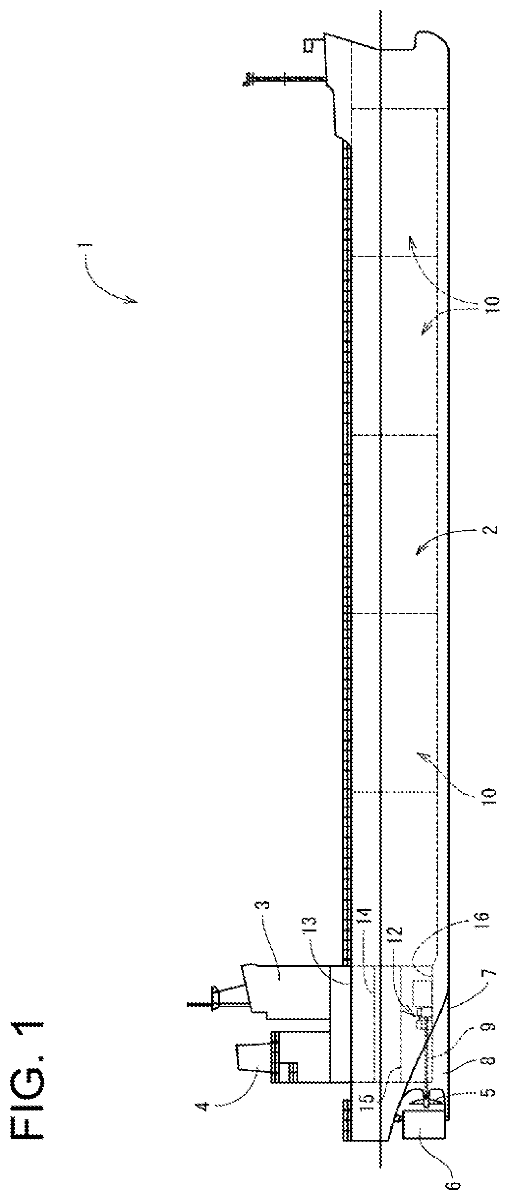
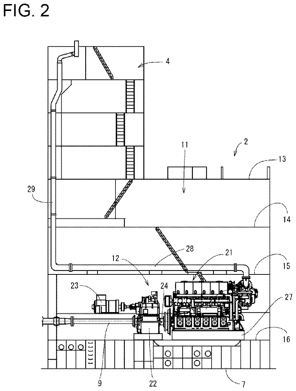
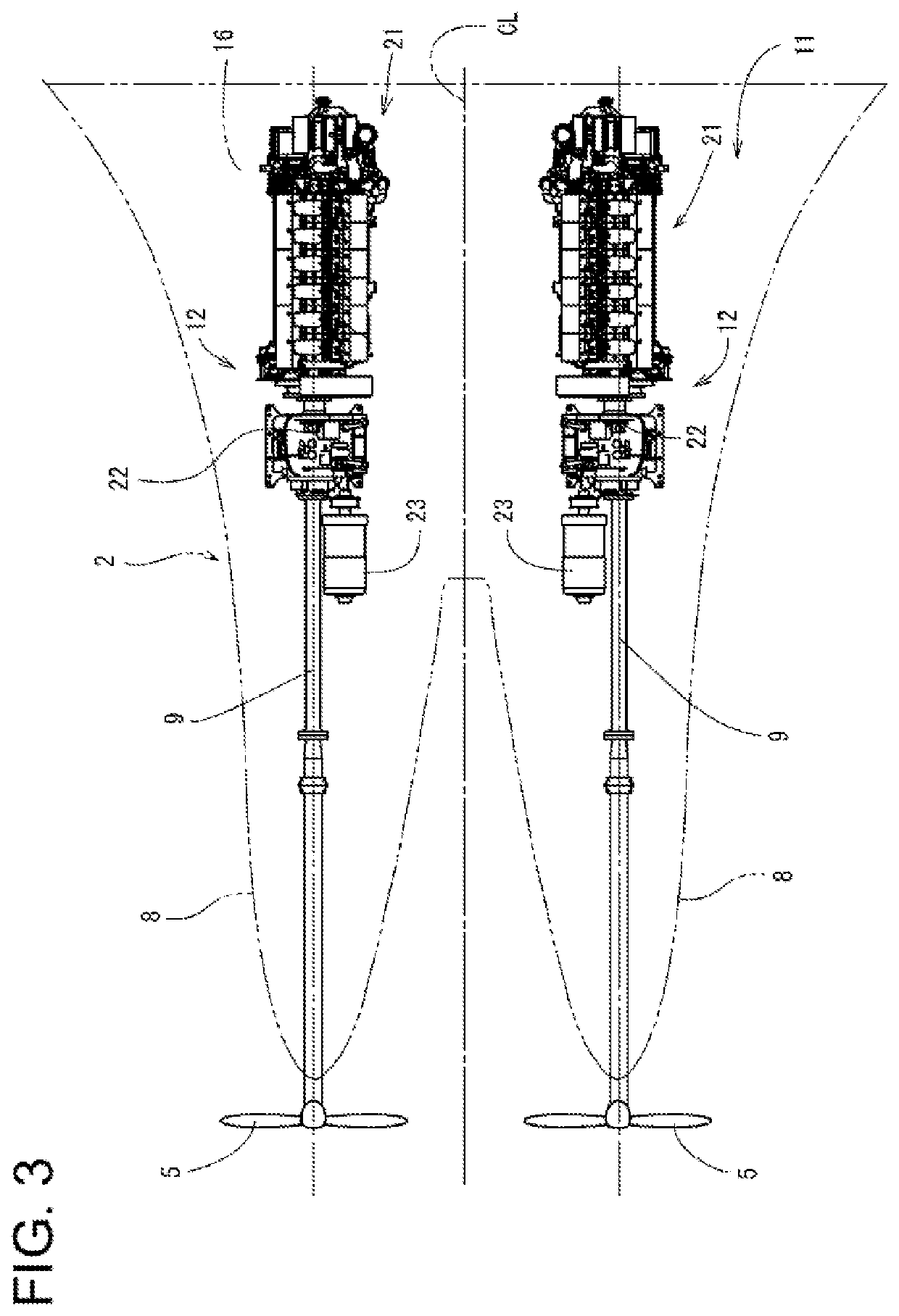
[0042]First, an overview of the ship is described. As shown in FIG. 1 to FIG. 3, the ship 1 of the present embodiment includes: a ship hull 2, a cabin 3 (bridge) provided on the stern side of the ship hull 2, a funnel 4 (chimney) positioned behind the cabin 3, and a pair of propellers 5 and a rudder 6 provided on a lower back portion of the ship hull 2. In this case, a pair of skegs 8 are integrally formed on the ship bottom 7 on the stern side. On each of the skegs 8, a propeller shaft 9 for driving to rotate the propeller 5 is pivotally supported. The skegs 8 are symmetrically formed on the left and right, with respect to the ship hull center line CL (see FIG. 3) which divides the lateral width direction of the ship hull 2. That is, the first embodiment adopts a twin skeg as the stern shape of the ship hull 2.

[0043]On a bow side and a middle part of the ship hull 2, a hold 10 is provided. On the stern side of the ship hull 2, an engine room 11 is provided. In the engine room 11, a...

second embodiment

[0113]As shown in FIG. 17, in the engine device 21 of the second embodiment, when the engine controlling device 73, during the gas mode operation (Yes in STEP 1), confirms an abnormality in the engine operation or the current location being outside the restricted sea area (Yes in STEP 2 or STEP 3), injection of the fuel gas from the gas injector 98 is stopped (STEP 4). That is, the engine controlling device 73 determines that the operation switching from the gas mode to the diesel mode is to be executed, and stops supply of the fuel gas to the cylinders 36 (cylinders 77).

[0114]Next, when the engine controlling device 73 confirms the cylinder 36 immediately before reaching the timing for injecting the fuel oil in the compressing stroke (STEP 105), and then confirms whether or not the fuel gas has been injected to that cylinder 36 in the immediately previous air intake stroke (STEP 106). At this time, in the cylinder 36 immediately before reaching the timing for injecting the fuel oil...


PUM


Abstract

An engine device of the present invention includes including: an intake manifold configured to supply air into a cylinder; an exhaust manifold configured to output exhaust gas from the cylinder; a gas injector which mixes a gaseous fuel with the air supplied from the intake manifold; and a main fuel injection valve configured to inject a liquid fuel into the cylinder for combustion. At the time of switching from a gas mode in which the gaseous fuel is supplied into the cylinder to a diesel mode in which the liquid fuel is supplied into the cylinder, a supply-start timing of the liquid fuel is delayed relative to a supply-stop timing of the gaseous fuel.

Description

CROSS REFERENCES TO RELATED APPLICATIONS[0001]This application is a national stage application pursuant to 35 U.S.C.§ 371 of International Application No. PCT / JP2016 / 065253, filed on May 24, 2016, which claims priority under 35 U.S.C. § 119 to Japanese Patent Application No. 2015-182481, filed on Sep. 16, 2015, the disclosures of which are hereby incorporated by reference in their entireties.TECHNICAL FIELD[0002]The present invention relates to an engine device of a multi-fuel adoptable type for both gaseous fuels such as natural gas and liquid fuels such as heavy oil.BACKGROUND ART[0003]Traditionally, diesel engines are used as a drive source of vessels such as tankers or transport ships and onshore power generation facilities. However, the exhaust gas of the diesel engine contains a large amount of nitrogen oxides, sulfur oxides, particulate matter, and the like which are harmful substances hindering preservation of the environment. For this reason, in recent years, gas engines th...

Claims


Application Information

Patent Timeline
Patent Type & Authority Patents(United States)
IPC IPC(8): F02D41/00F02D19/06F02D41/40F02D29/02F02D19/10F02D41/30B63H21/14
CPCF02D41/3047F02D19/105F02D19/0618F02D19/0642F02D29/02F02D41/401F02D19/0657F02D41/3064F02D19/0615F02D19/0686F02D41/0027F02D41/0025F02D2200/101Y02T10/44B63H21/14Y02T10/36F02D19/0613F02D41/345F02D41/3094F02D2200/701Y02T70/5218Y02T10/30Y02T10/40
Inventor HAGIWARA, RYOICHITOSHINAGA, KAZUTERUDOI, MASAYOSHIMURAKAMI, TAISHIOHSARA, TATSUROYAMAGISHI, OSAMU
Owner YANMAR POWER TECHNOLOGY CO LTD
Why Eureka
Try Eureka