Burner structure

a burner and burner technology, applied in the direction of burners, combustion types, pulverizing fuel combustion burners, etc., can solve the problems of difficult to achieve the desired distribution rate of the rich portion nozzle, affecting ignition performance or combustion stability, etc., to achieve low combustibility, high ignition performance and combustion stability

Inactive Publication Date: 2008-04-24
MITSUBISHI HEAVY IND LTD
View PDF18 Cites 5 Cited by
  • Summary
  • Abstract
  • Description
  • Claims
  • Application Information

AI Technical Summary

Benefits of technology

[0015] The present invention has been accomplished in view of the above circumstances, and it is an object of the present invention to provide a low combustibility fuel firing burner that can ensure high ignition performance and combustion stability even if a gas flow rate is changed along with changes in boiler load or the like.
[0021] In the low combustibility fuel firing burner, it is preferred that a wall against which a low combustibility fuel supplied into the separator collides be given a hardwearing finish. Thus, a wear resistance of the wall against which slag, melted ash, and unburnt carbon collide is improved.
[0023] According to the low combustibility fuel firing burner, a blowoff angle of the rich portion nozzle and a blowoff angle of the lean portion nozzle are offset in a vertical direction, so interference of flames of nozzles can be prevented.
[0025] According to the low combustibility fuel firing burner, a blowoff angle of the lean portion nozzle is offset to a furnace wall side in a horizontal direction, so it is possible to prevent slagging on a furnace wall as well as interference of flames of nozzles.
[0026] According to the present invention, in the low combustibility fuel firing burner structured to distribute fuel particles of a low combustibility fuel with a separator, it is possible to prevent changes in distribution rate in accordance with operation conditions or gas backflow, so high ignition performance and combustion stability can be ensured.
[0027] Further, high ignition performance and combustion stability can be ensured by preventing interference of flames of adjacent nozzles as well.

Problems solved by technology

However, according to the above related art, when a gas flow rate is changed along with change in boiler load or the like, an ignition performance or combustion stability might be affected thereby.
In particular, in the case of using a low combustibility fuel, an ignition performance or combustion stability is affected also by interference of flames of adjacent nozzles.
Therefore, it is difficult to attain a desired distribution rate for the rich portion nozzle 24 and the lean portion nozzle 26.
Further, if a burner is not used during partial load operations or a spare burner is used, there is a fear of backflow of a gas from the lean nozzle pipe 25 to a direction of the separator 20A due to a negative pressure.

Method used


Image

  • Burner structure
  • Burner structure
  • Burner structure

Examples


Embodiment Construction

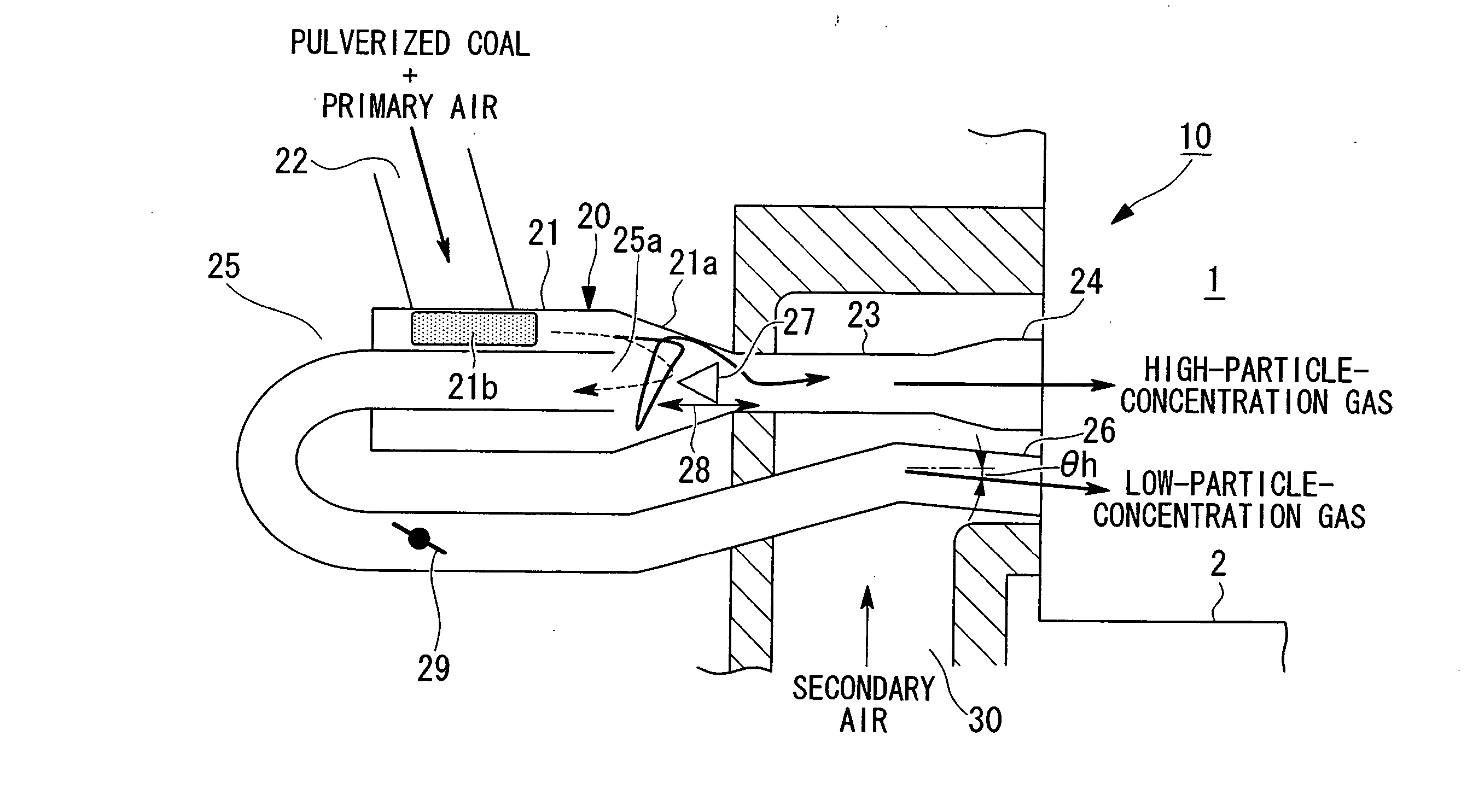
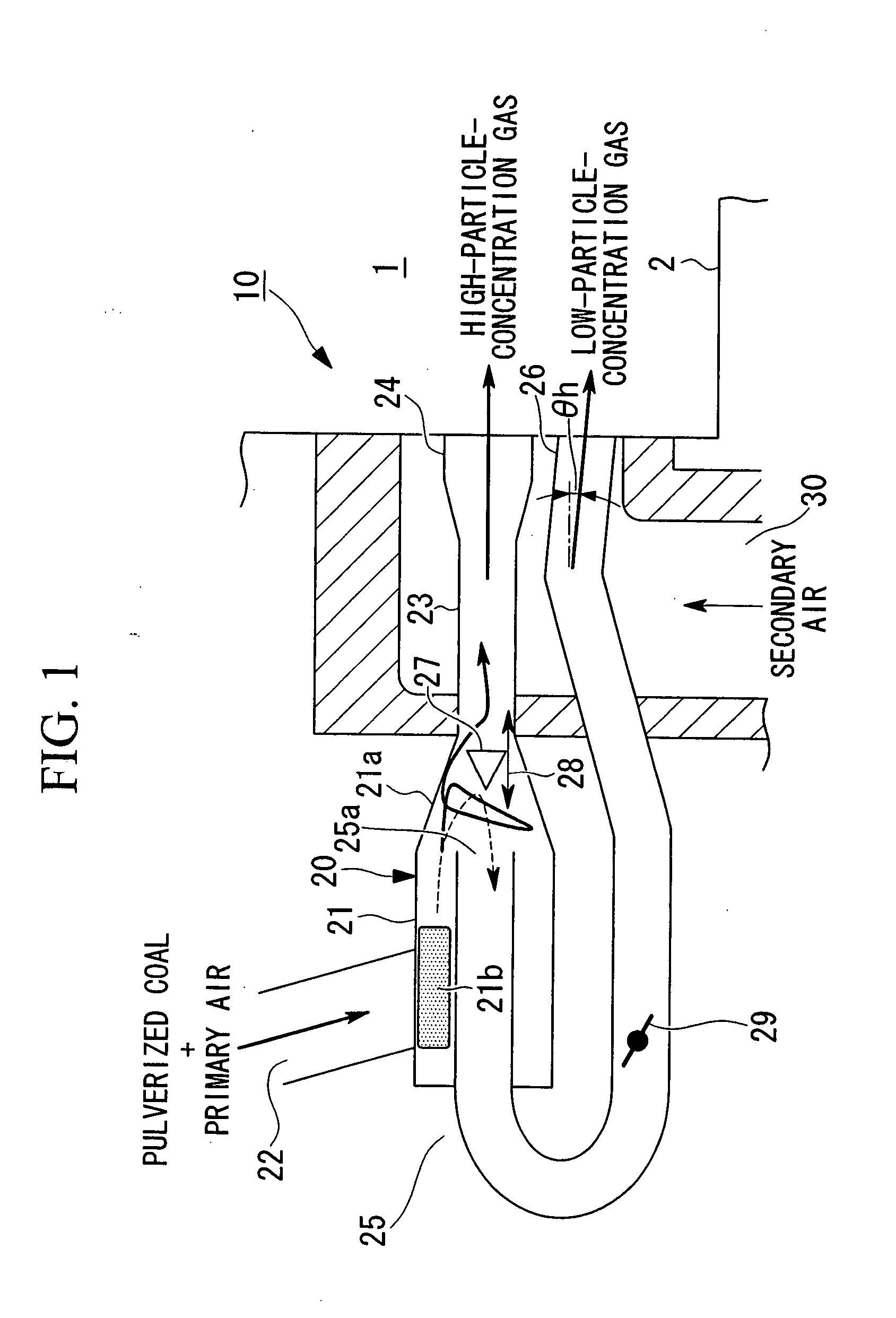
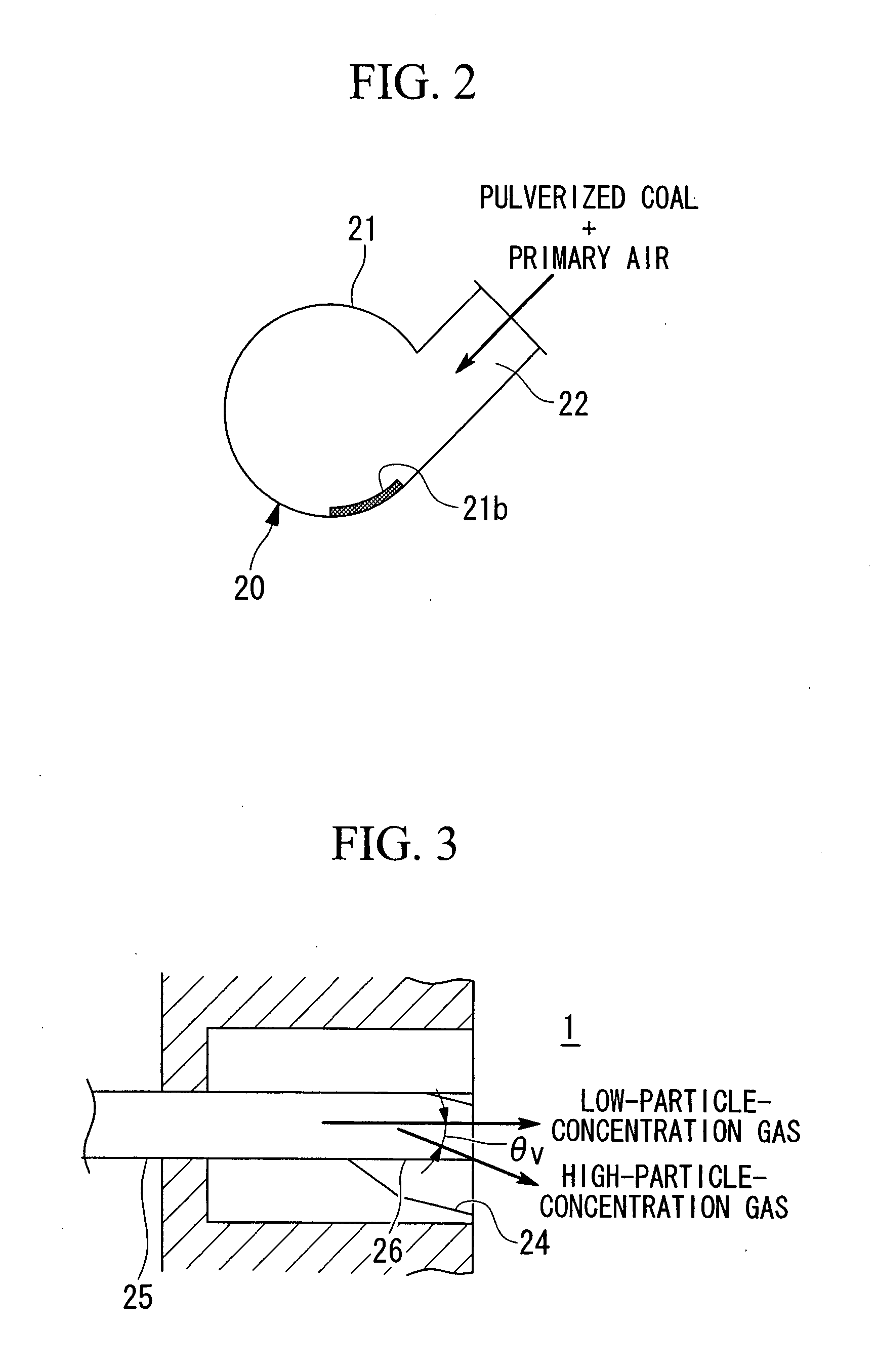
[0033] Hereinafter, an embodiment of a low combustibility fuel firing burner according to the present invention will be described with reference to the accompanying drawings.

[0034] A low combustibility fuel firing burner (hereinafter simply referred to as “burner”) 10 of FIGS. 1 to 3 is provided in, for example, a furnace 1 of a pulverized coal boiler or the like. The burner 10 burns a powder (fine powder) of a low combustibility fuel supplied together with an air in the furnace 1. Specific examples of the low combustibility fuel include anthracite and petroleum coke.

[0035] The following description is directed to the burner 10 supplied with a fuel that is pulverized coal obtained by pulverizing anthracite as a low combustibility fuel.

[0036] The burner 10 is composed of a pulverized coal supply system supplied with pulverized coal together with a primary air at a relatively low temperature, about 100° C., and a secondary air system supplied with a secondary air at a relatively hi...


PUM


Abstract

To provide a low combustibility fuel firing burner that can ensure high ignition performance and combustion stability even if a gas flow rate is changed along with changes in boiler load or the like. A low combustibility fuel firing burner separates a pulverized low combustibility fuel supplied together with an air with a separator, distributing the separated fuel to a rich portion nozzle and a lean portion nozzle provided in a furnace, and burning the fuel, in which a variable control part such as a core or a flow adjusting / blocking valve is provided in at least one of a high-particle-concentration gas pipe extending from a downstream side of the separator and communicating with the rich portion nozzle and a low-particle-concentration gas pipe extending from the downstream side of the separator and communicating with the lean portion nozzle.

Description

BACKGROUND OF THE INVENTION [0001] 1. Field of the Invention [0002] The present invention relates to a low combustibility fuel firing burner applicable to various types of combustion apparatuses that burn a low combustibility fuel such as a pulverized coal boiler. [0003] This application is based on Japanese Patent Application No. 2006-286692, the content of which is incorporated herein by reference. [0004] 2. Description of Related Art [0005] Hitherto, a low combustibility fuel firing burner that burns a pulverized low combustibility fuel (hereinafter referred to as “burner”) has been used in pulverized coal boilers fired with a low combustibility fuel such as anthracite or petroleum coke in a fine powder form. [0006] For example, as shown in FIGS. 4 and 5, a burner 10A of the related art, which burns a fuel that is pulverized coal obtained by pulverizing anthracite in a furnace 1 of a boiler is composed of a pulverized coal-air mixture system provided in the burner center and supp...

Claims


Application Information

Patent Timeline
Patent Type & Authority Applications(United States)
IPC IPC(8): F23D1/00
CPCF23D1/00F23K3/02F23D2201/20F23D1/04F23K3/00
Inventor TAKASHIMA, RYUHEIFUJIMURA, KOUTAROOKAMOTO, AKIYASUSUTO, TAKAYUKIAMANO, IWAMAROHIRATA, TOSHIHIRO
Owner MITSUBISHI HEAVY IND LTD
Why Eureka
Try Eureka