Gaseous fuel burner with high energy and combustion efficiency, low pollutant emission and increased heat transfer

a gaseous fuel burner and high energy and combustion efficiency technology, applied in the direction of burners, indirect carbon-dioxide mitigation, combustion types, etc., can solve the problems of low efficiency, low energy efficiency, and low efficiency in the heat transfer process, and achieve high energy and combustion efficiency, improved heat transfer, and greater heat transfer

Active Publication Date: 2018-01-30
RIVERA GARZA JORGE
View PDF25 Cites 2 Cited by
  • Summary
  • Abstract
  • Description
  • Claims
  • Application Information

AI Technical Summary

Benefits of technology

[0015]The main objective of the invention is to make available a gaseous fuel burner (including all mixtures thereof) which allows generating a highly turbulent mix between the fuel and the oxidant which allows to maximize the heat transfer and improve the combustion process to heat a bigger air mass, which translates to greater fuel savings and an important reduction of the emission of pollutant gases.
[0016]Other objective of the invention is to allow said gaseous fuel burner (including all mixtures thereof) of high energy and combustion efficiency and greater heat transfer as well, which also improves the heat transfer thus reducing the consumption of fuel up to 50% of what is normally used in conventional burners.
[0017]Other objective of the invention is to allow said gaseous fuel burner (including all mixtures thereof) of high energy and combustion efficiency and greater heat transfer as well, which allows reducing greenhouse gases emission up to 60% and reaching a category of low NOx emissions and therefore reach environmental protection standards required by law.

Problems solved by technology

However most show low energy efficiency since the combustion processes are low efficient and consume high quantities of fuel, combined with high pollutant emissions of NOx, CO and CO2.
Moreover conventional burners perform the combustion process outside the burner which lowers their efficiency in the heat transfer process.
The general structural configuration of this burners produces a mix of the gaseous fuel (including all mixtures thereof) and the oxidant in a laminar flow or hardly reaching the turbulent flow, which is not sufficient to excite the gas flow to liberate its maximum energy.
Although it prevents a high production of NOx, the configuration and geometric arrangement of the burner is such that it does not allow a more efficient combustion which translates to a higher energy efficiency, in addition the low injection speed of residual gas used increases the size of the boiler and poses greater safety issues.
However said burner does not feature a structure or geometric arrangement which allows neither a more efficient combustion process, nor good energy efficiency; moreover it requires the injection of preheated air.
However, the structural configuration and geometric arrangement of the burner prevents offering the characteristics and benefits provided by the gaseous fuel burner (including all mixtures thereof) of the invention.
However, the structural configuration and geometric arrangement of the burner also do not offer the benefits provided by the gaseous fuel burner (including all mixtures thereof) of the invention; moreover it shows that the flame is generated in the end part outside the burner.
This ratios do not achieve fuel savings and the heated air mass is reduced; moreover the levels of pollutant emissions to the atmosphere are very high.

Method used


Image

  • Gaseous fuel burner with high energy and combustion efficiency, low pollutant emission and increased heat transfer
  • Gaseous fuel burner with high energy and combustion efficiency, low pollutant emission and increased heat transfer
  • Gaseous fuel burner with high energy and combustion efficiency, low pollutant emission and increased heat transfer

Examples


Embodiment Construction

[0058]The characteristic details of the gaseous fuel burner (including all mixtures thereof) with high energy and combustion efficiency, low pollutant emissions and greater heat transfer are clearly shown in the following description and in the attached illustrative drawings, which serve as reference highlight the same parts.

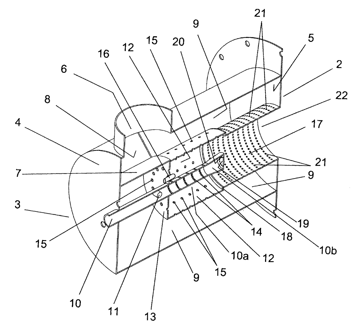
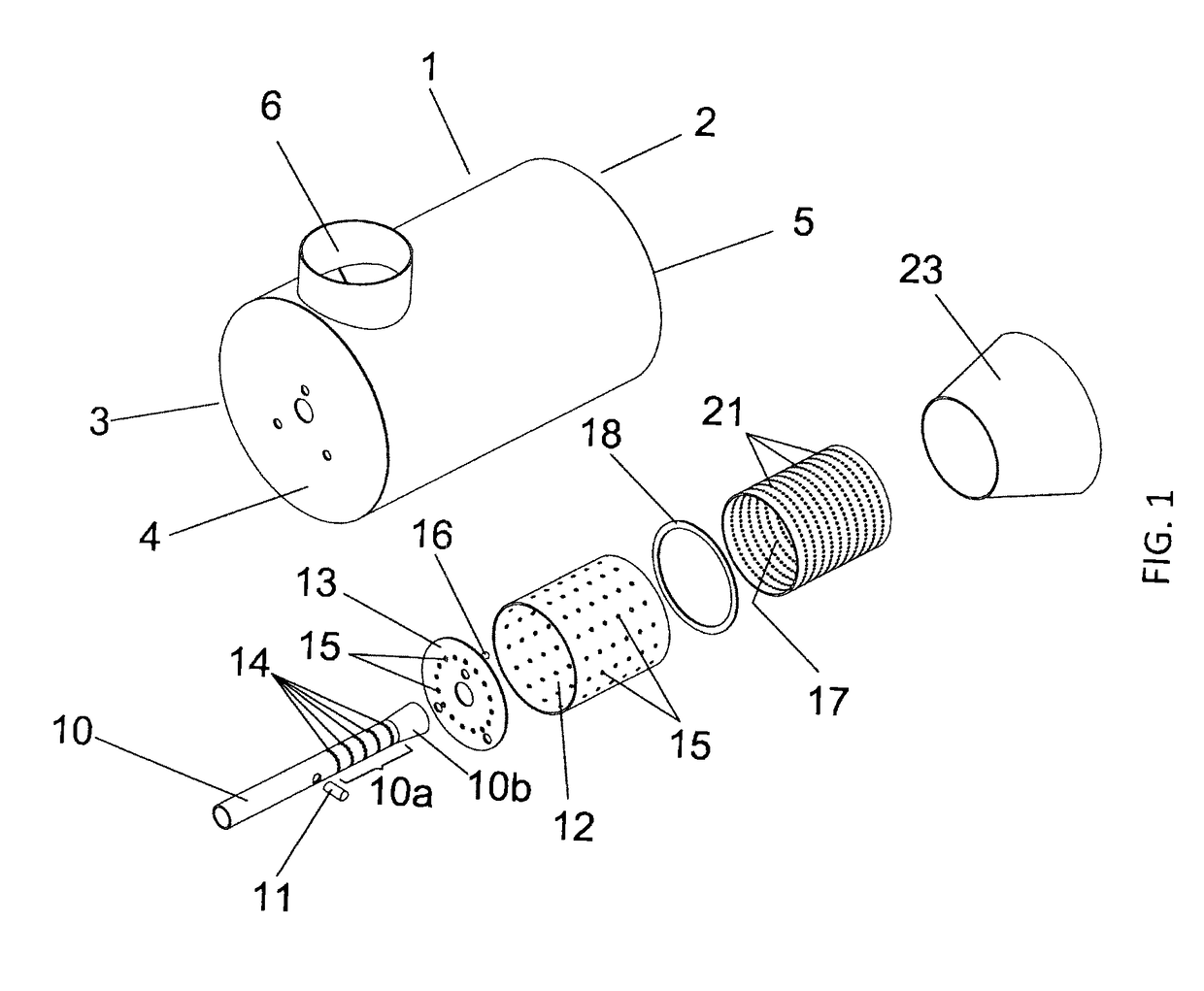
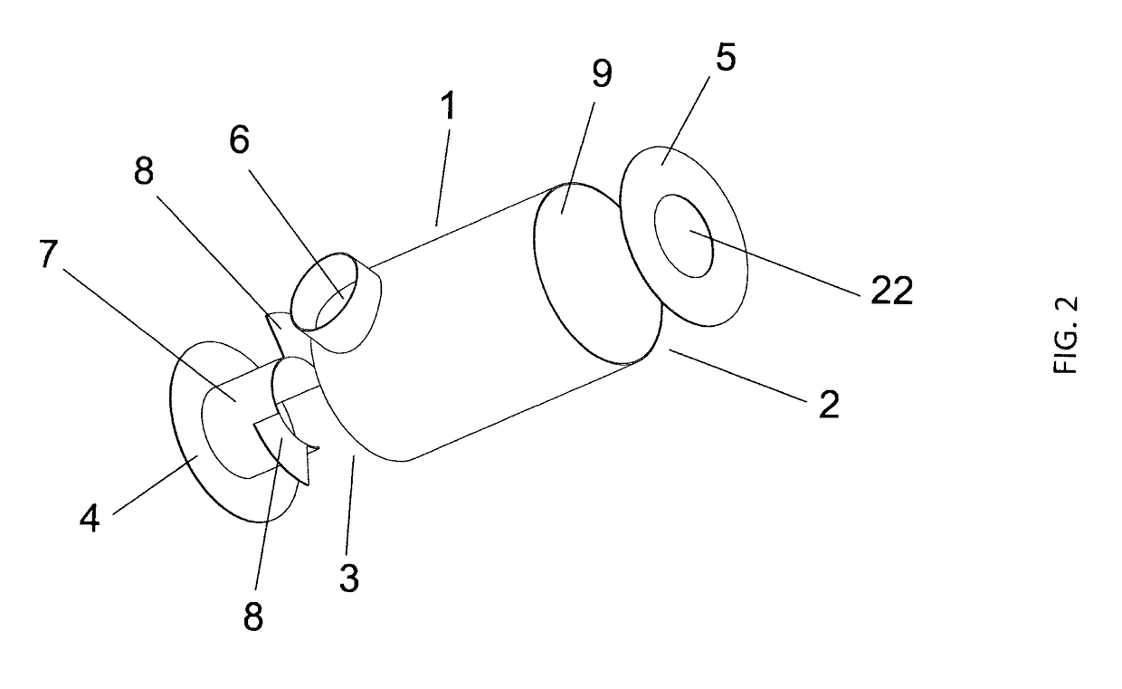
[0059]Making reference to FIGS. 1 and 4, the burner consists of an outer housing 1 which defines a distal end 2 of outlet for the flame and a proximal end 3 of supply of the gaseous fuel (including all mixtures thereof) and oxidant (air); both ends having covers 4 and 5; a pressurized air inlet 6 is placed radially on the wall of the housing close to the proximal end 3, in which interior a concave deflector 7 is placed in the zone of the inlet of pressurized air 6 and is attached in said cover 4 of the proximal end 3; at least two deflector plates 8 separated between each other and radially fixed on the inner wall of said housing 1 and in said concave deflector ...


PUM


Abstract

The invention relates to a gaseous fuel (including all mixtures thereof) burner structure, characterized in that it comprises: a housing defining a distal flame outlet end and a proximal gaseous fuel and air supply end, both ends having covers; a pressurized-air inlet arranged in the housing close to the proximal end, defining an inner pressurized-air-supply chamber; a pressurized-gaseous-fuel-supply duct arranged in the center, housed in a first mixing chamber and provided with a plurality of openings for the outflow of the gaseous fuel to said first mixing chamber, said first mixing chamber also comprising a plurality of openings for supplying pressurized air axially and radially; an igniter arranged inside said first mixing chamber for a first combustion; a second, over-mixing chamber arranged colinearly with said first chamber, the end of the fuel duct comprising a cover provided with openings via which gaseous fuel is axially supplied to said second, over-mixing chamber, and the wall of said second chamber comprising openings via which pressurized air is radially supplied, where a second stage of the combustion process is carried out; and a third, conical flame-formation chamber colinearly connected to the end of said second, over-mixing chamber.

Description

CROSS REFERENCE TO RELATED APPLICATIONS[0001]The present application is a National Stage of International Application No. PCT / MX2013 / 000061, filed on May 14, 2013, which claims priority to Mexican Application No. MX / a / 2012 / 006599, filed on Jun. 8, 2012, the entire contents of which are being incorporated herein by reference.FIELD OF THE INVENTION[0002]The invention relates to an innovative gaseous fuel burner structure (including all mixtures thereof), which produces a highly turbulent mix between the gaseous fuel (including all mixtures thereof) and the oxidant, which has a high energy efficiency, low pollutant emissions and generates turbulent kinetic energy, which makes the combustion process more efficient and generates a greater heat transference which allows heating a bigger air mass at higher temperatures.BACKGROUND OF THE INVENTION[0003]Generally all the gaseous fuel burners and all their mixtures (e.g. natural gas, LP gas, hydrogen, etc.) have the same application, that is ...

Claims


Application Information

Patent Timeline
Patent Type & Authority Patents(United States)
IPC IPC(8): F23D14/02F23D14/70F23D14/22F23D14/62F23D14/58
CPCF23D14/02F23D14/22F23D14/58F23D14/62F23D14/70F23D2203/102F23C2201/20F23C2900/03005F23C2900/06041Y02E20/34
Inventor RIVERA GARZA, JORGE
Owner RIVERA GARZA JORGE
Why Eureka
Try Eureka