
Multi-stage combustion using nitrogen-enriched air

a technology of nitrogen-enriched air and combustion system, which is applied in the direction of solid fuel combustion, machines/engines, lighting and heating apparatus, etc., can solve the problems of not meeting the impending requirements of greatly reduced no/sub>x/sub>, the maximum operational temperature of most combustion system, especially continuous flow one, is limited, etc., to reduce corrosive and oxidative gases, increase fuel efficiency, and reduce pollution. exhaust emissions

Inactive Publication Date: 2005-02-03
LAWRENCE LIVERMORE NAT SECURITY LLC
View PDF9 Cites 8 Cited by
  • Summary
  • Abstract
  • Description
  • Claims
  • Application Information

AI Technical Summary

Benefits of technology

It is an object of the present invention to increase fuel efficiency in combustion systems while simultaneously reducing polluting exhaust emissions.
A further object of the invention is to provide a combustion system which controls the combustion temperature and products so as to extend the maintenance and lifetime cycles of materials in contact with the combustion products and reduce pollutants while maintaining relatively high combustion and thermal cycle efficiencies.
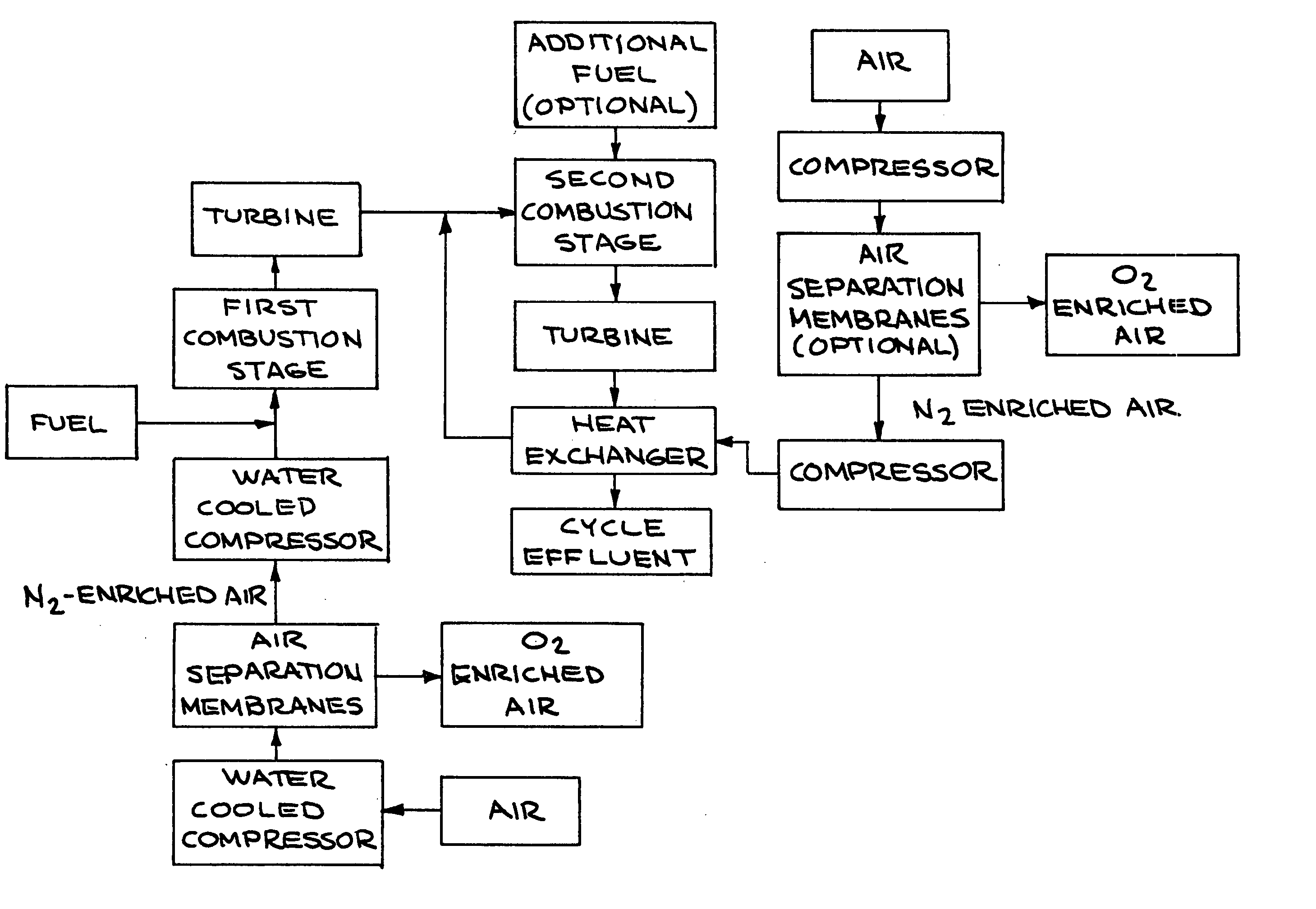
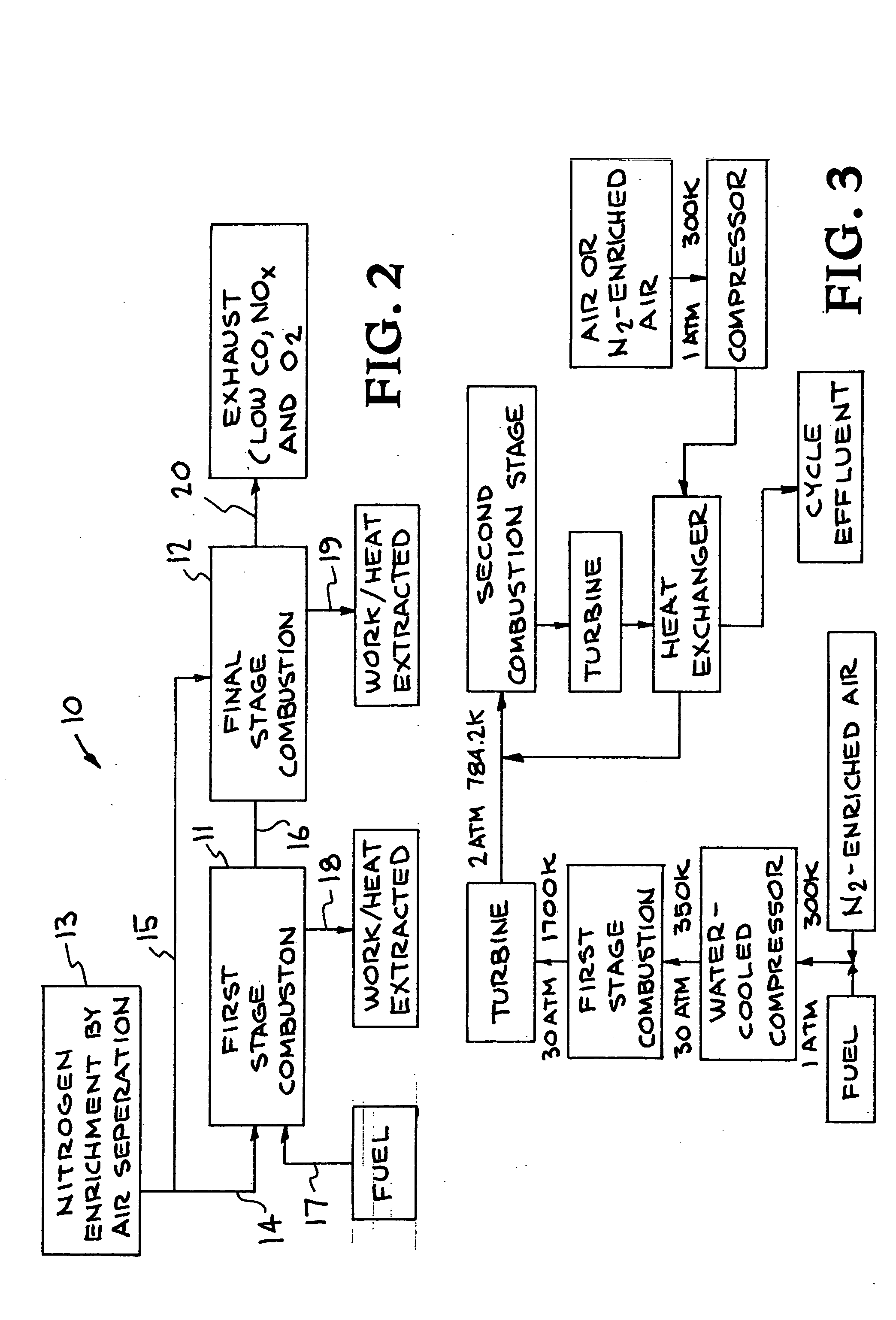
Other objects and advantages of the present invention will become apparent from the following description and accompanying drawing. The invention is a multi-stage combustion system using nitrogen-enriched air. The combustion system of this invention can increase fuel efficiency while simultaneously reducing polluting exhaust emissions. For example, a two-stage turbine can be used to reduce the corrosive and oxidative gases by burning fuel rich in the first stage and stoichiometrically in the second stage, with the combustion temperature being reduced by the use of nitrogen augmentation or enriched air. By operating the first stage of combustion by burning the fuel with nitrogen-enriched air, most of the heat of combustion is released in the burning process, part of the energy in the combustion gases being used to perform work or to provide heat, and the cooled combustion gases are reheated by additional stages of combustion until the last stage is at or near stoichiometric conditions. Additional energy is extracted from each stage to result in relatively high thermal cycle efficiency. The air is enriched with nitrogen using air separation technologies such as diffusion, premeable membrane, absorption, and cryogenics. The invention has application for various types of combustion systems including turbines, boilers, furnaces, as well as combustion engines, and various types of fuels can be utilized including hydrogen, coal, methane, and various other carbon-based fuels.

Problems solved by technology

Also, the combustion gases can be very corrosive with the excess oxygen and reduce the life of the engine.
Past research developed efficient engines by operating with equivalence ratios less than one, but will not meet impending requirements for greatly reduced NOx.
The maximum operational temperature of most combustion systems, especially continuous flow ones, is limited by the materials of construction and the corrosive and oxidative products of combustion.
In general, higher operational temperatures decrease the materials physical properties (e.g., strength) and increase corrosion and oxidation of the material.
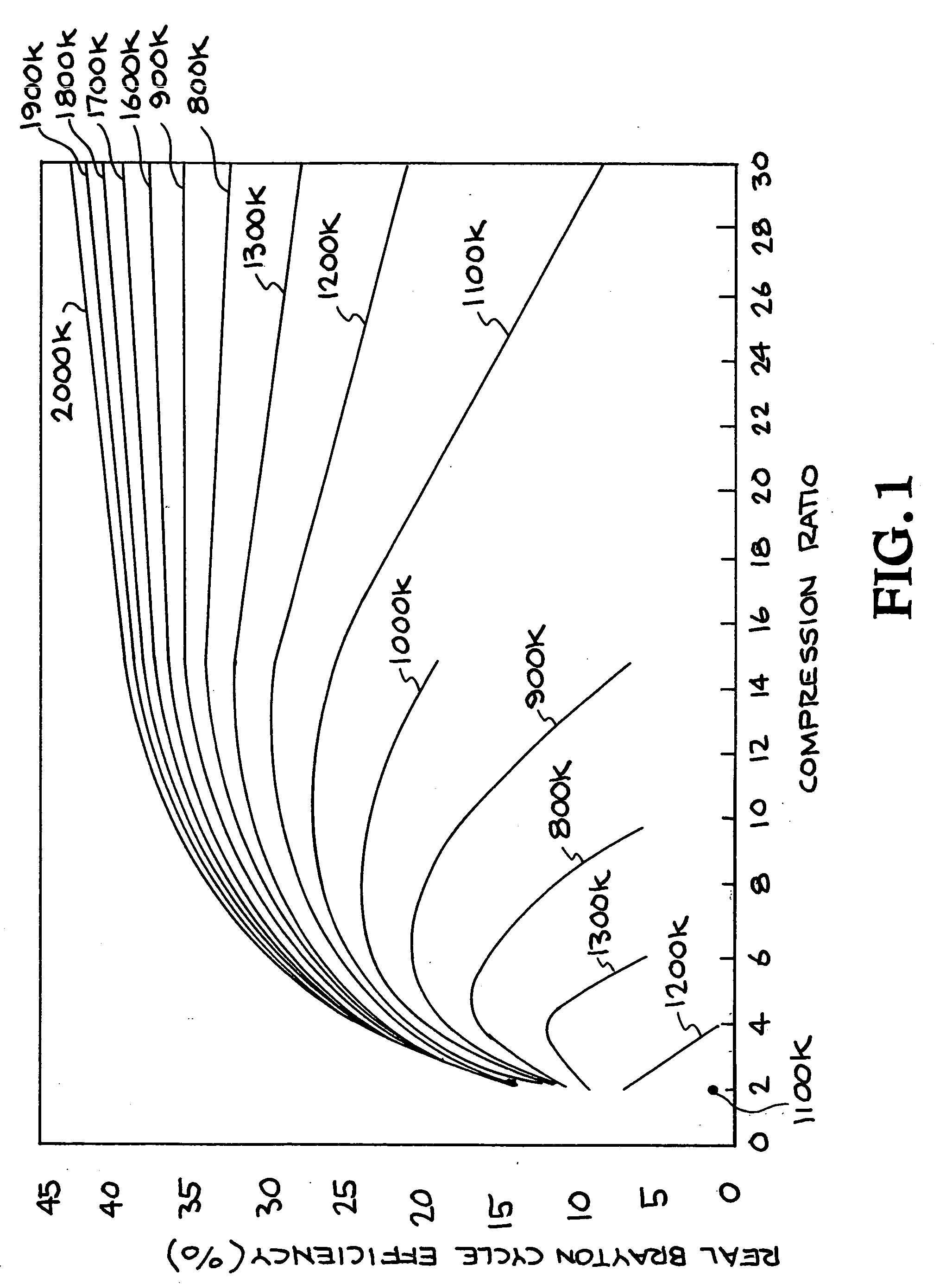
Typically, gas turbines operate with excess air (Φ=0.4-0.7) to reduce the operational temperature but produces large amounts of corrosive, and oxidative gases.
However, in order to obtain acceptable combustion temperatures in the first stage, the fuel ratio tends to be excessively high which can result in soot formation and fouling.

Method used


Image

  • Multi-stage combustion using nitrogen-enriched air
  • Multi-stage combustion using nitrogen-enriched air
  • Multi-stage combustion using nitrogen-enriched air

Examples


Embodiment Construction

The present invention is directed to multi-stage combustion using nitrogen-enriched air. The combustion approach of this invention results in lower pollutant emissions, lower corrosion rates of combustion and heat-transfer equipment, and comparable or improved efficiencies as compared to the typical combustion process used in boilers, burners, turbines, and internal combustion engines. This combustion approach combines the technologies of stage-combustion with the use of nitrogen-enriched air for the oxidant stream in one or more of the combustion stages.

The high oxidant loading in the effluent from many combustion processes facilitates large corrosion rates in the related combustion and process equipment, especially the equipment that is in contact with high-temperature effluent. The high oxidant concentration typically results from the single-stage burning of fuel “lean” (more than the stoichiometric amount of air) to control the combustion temperature, the corrosion rate, and ...


PUM


Abstract

Multi-stage combustion technology combined with nitrogen-enriched air technology for controlling the combustion temperature and products to extend the maintenance and lifetime cycles of materials in contact with combustion products and to reduce pollutants while maintaining relatively high combustion and thermal cycle efficiencies. The first stage of combustion operates fuel rich where most of the heat of combustion is released by burning it with nitrogen-enriched air. Part of the energy in the combustion gases is used to perform work or to provide heat. The cooled combustion gases are reheated by additional stages of combustion until the last stage is at or near stoichiometric conditions. Additional energy is extracted from each stage to result in relatively high thermal cycle efficiency. The air is enriched with nitrogen using air separation technologies such as diffusion, permeable membrane, absorption, and cryogenics. The combustion method is applicable to many types of combustion equipment, including: boilers, burners, turbines, internal combustion engines, and many types of fuel including hydrogen and carbon-based fuels including methane and coal.

Description

BACKGROUND OF THE INVENTION The present invention relates to combustion systems, particularly to increasing the efficiency of combustion systems while simultaneously reducing polluting exhaust emissions, and more particularly to a combustion system which combines multi-stage combustion technology with nitrogen-enriched air technology. Increasing fuel efficiency in combustion engines while simultaneously reducing polluting exhaust emissions has been researched over the past 25 years and subsidized by the Federal Government. Maximum fuel efficiency normally occurs at or near stoichiometric conditions where the fuel is completely oxidized. In practice, the combustion process in an engine is usually with air and not with pure oxygen. When oxygen is supplied by dry air, 3.76 moles of nitrogen will accompany one mole of oxygen. The stoichiometric air-fuel ratio is the ratio of the mass of air to the mass of fuel to result in stoichiometric combustion. The actual operating condition of a...

Claims


Application Information

Patent Timeline
Patent Type & Authority Applications(United States)
IPC IPC(8): F02B1/12F02M25/00F23C6/04F23L7/00F23R3/34
CPCF02B1/12F02M25/00F23C6/045F23R3/346F23L7/00F23L2900/07002F23C2900/06041Y02E20/34
Inventor FISCHER, LARRY E.ANDERSON, BRIAN L.
Owner LAWRENCE LIVERMORE NAT SECURITY LLC
Learn More