
EGR system and engine

A technology for engines and four-valve engines, which is applied to engine components, machines/engines, charging systems, etc., and can solve problems such as unfavorable engine economy, adverse effects on engine performance, and mutual interference of exhaust harmonics

Inactive Publication Date: 2019-09-13
WEICHAI POWER CO LTD
View PDF5 Cites 2 Cited by
  • Summary
  • Abstract
  • Description
  • Claims
  • Application Information

AI Technical Summary

Problems solved by technology

[0003] At present, the commonly used EGR air intake method is to extract air from the exhaust manifolds of cylinders 1, 2, and 3 and from the exhaust manifolds of cylinders 4, 5, and 6 respectively, but this air intake method may be different due to different cylinders. Exhaust harmonics interfere with each other, affect the effect of EGR intake air, and may affect the uniformity of EGR rate of each cylinder; in addition, there are many other methods commonly used to increase EGR rate, such as VGT (Variable geometry turbocharger, variable cross-section turbocharger Compression system), small turbocharger, etc., will increase the pumping loss, which will have an adverse effect on the performance of the engine, which is not conducive to the economy of the engine

Method used


Image

  • EGR system and engine
  • EGR system and engine

Examples


Embodiment Construction

[0017] The following will clearly and completely describe the technical solutions in the embodiments of the present invention with reference to the accompanying drawings in the embodiments of the present invention. Obviously, the described embodiments are only some, not all, embodiments of the present invention. Based on the embodiments of the present invention, all other embodiments obtained by persons of ordinary skill in the art without making creative efforts belong to the protection scope of the present invention.

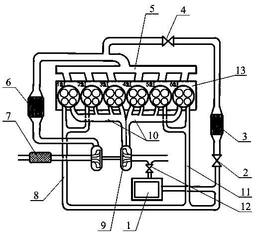
[0018] Please refer to figure 1 , figure 1 It is a schematic diagram of the EGR system in a specific embodiment of the present invention.

[0019] The invention provides an EGR system, the main purpose of which is to make full use of the exhaust pulse of the engine to improve the gas intake efficiency of EGR. When the EGR rate obtained by using the exhaust pulse cannot meet the requirements, the EGR gas after the turbine can Pressurization increases the EGR ...


PUM


Abstract

The invention discloses an EGR system and an engine. The EGR system is used for a multi-cylinder four-valve engine. Each cylinder of the engine is provided with a first exhaust passage and a second exhaust passage. The EGR system comprises an EGR gas pipe. A gas inlet of the EGR gas pipe is connected with the first exhaust passages of the at least two cylinders. The spaced crank angle of exhaust strokes of every two adjacent cylinders connected with the EGR gas pipe is greater than or equal to 180 degrees CA. A gas outlet of the EGR gas pipe is connected to a gas inlet pipe of the engine. According to the EGR system, the first exhaust passages of the two or more cylinders of the engine are connected to the EGR gas pipe; exhaust gas of the first exhaust passages is directly taken as an EGRgas source; meanwhile, the exhaust strokes of the adjacent cylinders are staggered, the offsetting and interference effect of exhaust pulses of the two adjacent cylinders is reduced; and accordingly,the exhaust pulses of the engine can be made full use of to improve the EGR gas taking efficiency, and then the EGR rate is increased.

Description

technical field [0001] The invention relates to the technical field of engines, in particular to an EGR system and an engine. Background technique [0002] With the stricter NOx emission standards, the performance and emission requirements of internal combustion engines are also getting higher and higher, and the EGR (Exhaust Gas Return, exhaust gas recirculation) technology has been paid more and more attention. In order to meet higher emission regulations, most of the current mainstream heavy-duty diesel engine manufacturers have chosen the technical route of high-pressure EGR (HP-EGR for short). The use of EGR technology can greatly reduce NOx emissions. According to relevant materials, when the EGR rate is 15% When the EGR rate is increased to 25%, the NOx emission can be reduced by more than 80%. [0003] At present, the commonly used EGR air intake method is to extract air from the exhaust manifolds of cylinders 1, 2, and 3 and from the exhaust manifolds of cylinders ...

Claims


Application Information

Patent Timeline
IPC IPC(8): F02M26/07F02M26/42F02M26/34
CPCF02M26/07F02M26/34F02M26/42
Inventor 尹晓军刘培杰王波张广全王井山康天钦
Owner WEICHAI POWER CO LTD
Learn More