Closeable self-venting spout

a self-venting, spout technology, applied in the direction of pliable tubular containers, liquid handling, packaging goods types, etc., can solve the problems of waste of materials, toxic or otherwise dangerous or damaging to persons or things in the surrounding area, and the size of the opening in the filling container may not be compatible with the size of the opening, etc., to achieve the effect of reducing leakage and spillage, reducing the length and shape, and releasing excessive container pressur

Inactive Publication Date: 2009-11-24
NITEC NIELSEN IDAHO TOOL & ENG
View PDF35 Cites 17 Cited by
  • Summary
  • Abstract
  • Description
  • Claims
  • Application Information

AI Technical Summary

Benefits of technology

[0012]An object of the present invention is to provide a spout that allows for regular flow of material through a valve system, formed within a portion of the spout, which provides for decreased leaks and spills. A preferred feature is to provide a closable spout of sufficient length and shape to give free access between the opening in the receiving tank and the filling tank, while being adapted for detachment, inversion, and insertion inside the filling container, for example, for storage and shipping inside a typical gas-can type filling container. Another preferred feature is to provide a sealing system in the spout that does not utilize an O-ring, and especially that does not utilize an O-ring installed on, or sealing with, a sliding element, as such O-rings have been known to swell and fail from contact with gasoline. A further object of the preferred embodiments is to provide a spout adapted to easily release excessive container pressure prior to use.
[0013]The self-venting spout comprises a valve system wherein the sliding of an internal valve sleeve, in one direction, seals closed both a liquid passageway and an air passageway, and, in the opposite direction, opens both of said liquid and air passageways. The valve sleeve may be actuated by an external actuation member such as a sheath, which is operatively linked to the valve sleeve by a wire, clip, or other connecting member extending from the sheath through the spout body and into the spout interior to reach the sleeve. Preferably, the liquid and air passageway openings at the dispensing end of the spout are entirely or substantially longitudinal (parallel to the length of the spout) rather that transverse, which minimizes or prevents the splash and leaking typically associated with “sideways” flow out of a filling spout. Further, the preferred valve sleeve and its actuation system are adapted so that there is some leeway in the actuation structure to prevent leaking of the spout due to manufacturing tolerances, and / or upon a small movement, impact, or jiggling of the actuation member. This may be accomplished, for example, by providing a physical gap in the actuation system, so that some movement of the actuation member and / or the connecting member may occur without the valve sleeve becoming dislodged from its liquid and air passageway sealing position. This way, an intentional effort, rather than a tap or bounce, is needed to unseal the valve so that leaking is minimized or eliminated during transport and handling of the device.
[0018]The preferred liquid-flow passageway portion may comprise a proximal portion near the liquid-inlet end of the spout housing and a distal portion near the liquid-outlet end of the spout housing. Preferably, the distal portion is smaller in volume than the proximal portion for creating a venturi effect as the liquid flows through said liquid-flow passageway portion toward the liquid-outlet end.
[0021]The invention may also comprise a system which comprises the combination of a liquid container and a spout. The spout may be described as having a first end connected to the liquid container, a second end adapted for dispensing liquid from the spout, and an internal passageway from said first end to said second end having a liquid-flow passage and an air-flow passage. The spout may further comprising a slidable sleeve inside the spout and configured to slide to a spout-closed position wherein the slidable sleeves seals the liquid-flow passage closed and slidable in an opposite direction to a spout-open position wherein liquid-flow passage is open for dispensing of liquid. The slidable sleeve may be operatively connected to a movable member on an outside surface of said spout that moves said slidable sleeve inside the spout between said spout-closed and spout-open positions. The slidable sleeve may seal the air-flow passage closed when said slidable sleeve is in the spout-closed position, but the air-flow passage is open for venting of the liquid container when said slidable sleeve is in the spout-open position. The preferred liquid passageways and the operative connection between the moveable member and the slidable sleeve are adapted to minimize or eliminate transverse liquid flow and openings / apertures through the spout housing and especially the half of the spout that is typically orientated at the bottom when the spout is in use filling the receiving container. This lack of openings / apertures in the “bottom” half of the spout prevents leakage / seepage that might otherwise occur if such openings / apertures were present.

Problems solved by technology

In the process of pouring gasoline or other material from one container into another, a variety of problems arise.
One problem is that the size of the opening in the filling container may not be compatible with the size of the opening on the receiving container.
As a result, the material being transferred may splash or flow over the outer portions of the container being filled.
When this occurs, the spilled material is not only wasted but may also be toxic or otherwise dangerous or damaging to persons or things in the surrounding area.
Spilled liquid gasoline may damage the surrounding environment, including soil, plants, and water, and the spilled gasoline also emits fumes that can be hazardous due to inhalation and increased risk of flammability.
However, these nozzles and spouts bring with them a variety of problems as well.
One of the problems with many of these types of nozzles is their inability to allow for a smooth transfer of air into the filling container to replace the liquid that is leaving the container, thus forming a vacuum within the filling container.
When sufficient pressure is built up, however, the vacuum is broken and liquid will surge forward out of the filling container.
This chugging or gurgling makes difficult the filling of a receiving container to a desired level without spilling, because the quantity of material that will surge forward is unpredictable.
Thus, this uneven liquid flow contributes to spillage and / or over filling of the container.
Another problem that exists in the prior art is that access to these filling containers may be obtained by small children, who may inhale the fumes or ingest the gasoline and suffer significant damaging effects.
Another problem that exists in the prior art is the use of O-rings as sealing systems, and, typically, the use of O-rings on moving valve elements.
O-rings seal by simply overpowering the material that they are sealing against, and, as a result, O-rings place substantial static pressures upon, and may cause failure of, various pieces of the spout.
Over time, the O-rings themselves, especially those provided on moving elements, may wear out or be degraded by the chemicals that they are trying to seal.
Another problem with such devices is that they can be prohibitively expensive to manufacture and produce.

Method used


Image

  • Closeable self-venting spout
  • Closeable self-venting spout
  • Closeable self-venting spout

Examples


Embodiment Construction

[0044]While embodiments of the invention may be modified and alternatively constructed, certain embodiments have been shown in the drawings and will be described below in detail. It should be understood, however, that there is no intention to limit the invention to the specific forms disclosed, as the invention is to cover all modifications, alternative constructions, and equivalents falling within the spirit and scope of the invention as defined in the claims.

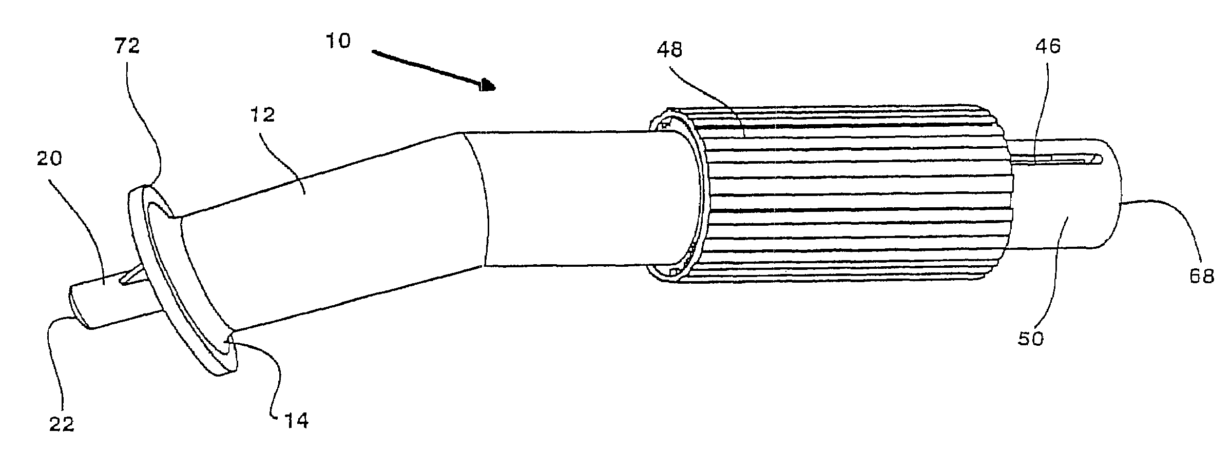
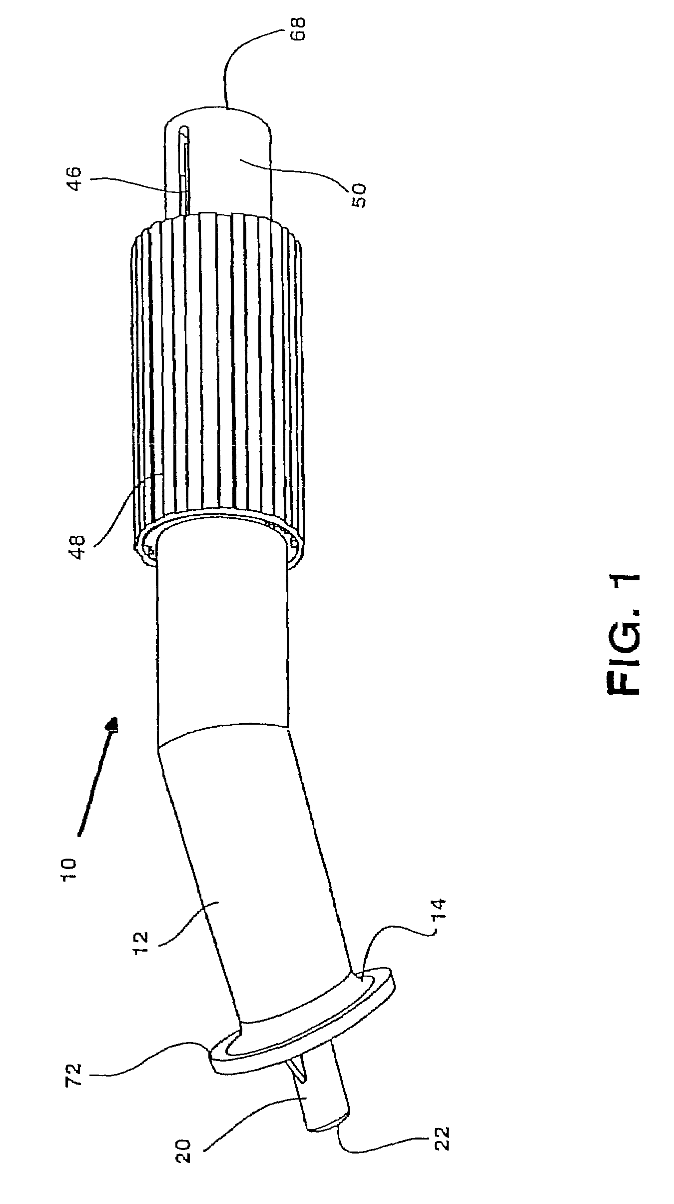
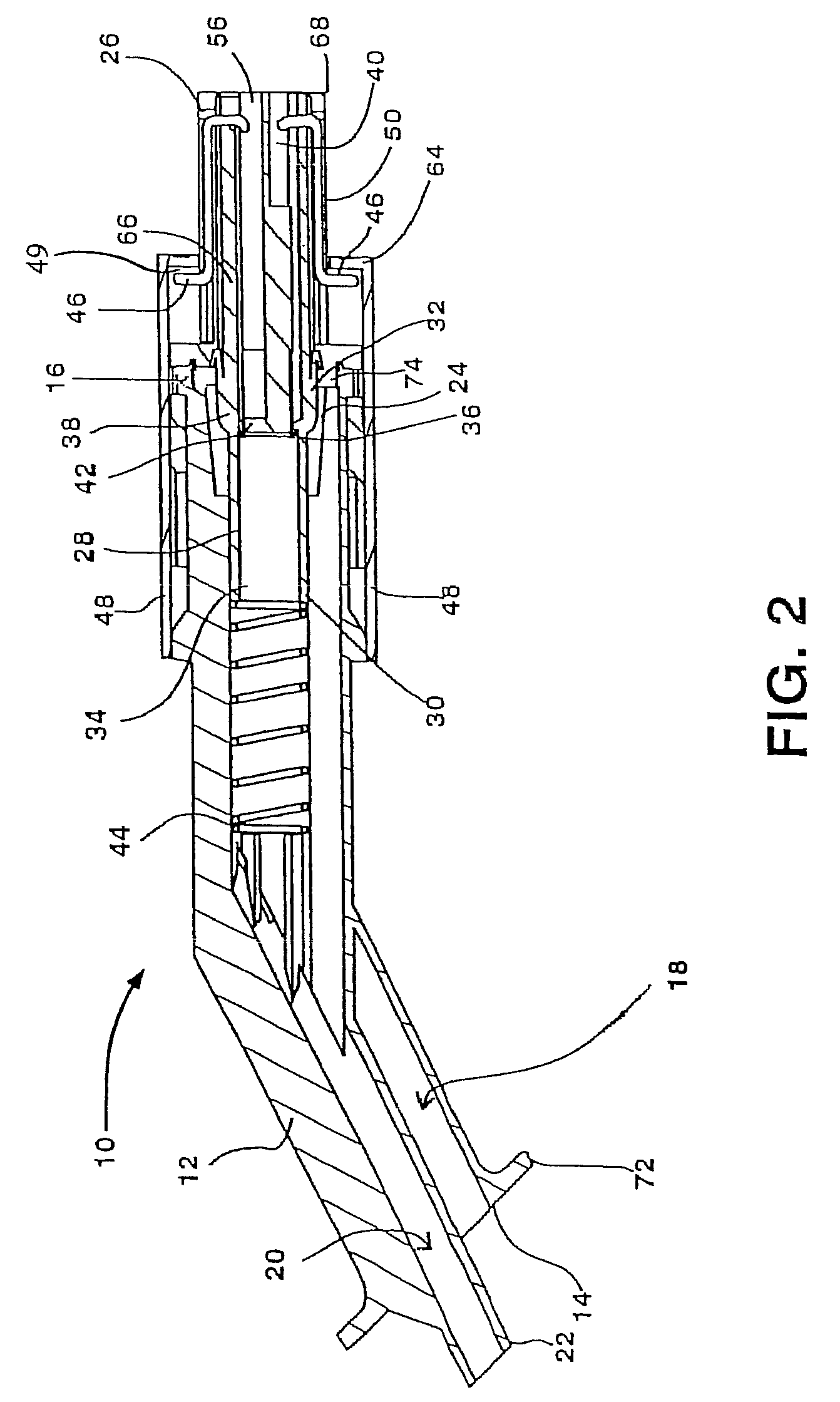
[0045]The preferred self-venting pouring spout is especially-well adapted for a non-vented filling container. The spout housing may be made of one or more pieces / units, but in the embodiments shown, the housing comprises a single one-piece tube as a spout body, and a nozzle unit or “nozzle end”. The spout body comprises a first hollow passageway with an open spout first end and an open spout second end, wherein the spout body connects at its second end to the nozzle unit.

[0046]A generally hollow tubular inner conduit is formed...


PUM

PropertyMeasurementUnit
oblique angleaaaaaaaaaa
lengthaaaaaaaaaa
diameteraaaaaaaaaa

Abstract

A non-spilling, detachable pouring spout is configured to transfer liquid from a non-vented filling container to a receiving container. The spout has a spout body defining a first hollow passageway extending from an open first end to an open second end, wherein this open passageway having a generally tubular hollow inner conduit positioned within the first hollow passageway and defining a second hollow passageway. An intermediate sleeve is received in the spout and seals against portions of the spout body and the inner conduit so as to variously control the flow of materials out of the spout body, preferably the flow of liquid out of the spout and air into the spout as a venting system. The movement of said sleeve may be controlled by movement of an external sheath and may include child-resistant features. The preferred spout may achieve smooth air venting and liquid flow, and minimizes transverse / sideways flow and openings that tend to cause splash and leaks. The preferred spout does not use any O-ring members, which are prone to failure when used with gasoline, but instead uses a slidable sleeve with inner and outer seal surfaces provided by a flared or bell-shaped seal member.

Description

[0001]This application claims priority of Provisional Application Ser. No. 60 / 798,148, filed May 5, 2006, and entitled “Closeable Self-Venting Spout,” which is hereby incorporated by reference.BACKGROUND OF THE INVENTION[0002]1. Field of the Invention[0003]The present invention generally relates to pouring spouts that are configured to transfer the contents of a storage or transfer container to a receiving container. More particularly, the present invention relates to a self-venting pouring spout that can be selectively opened and closed, and, preferably, may be automatically opened upon insertion into the opening of the receiving container. The preferred embodiment is a selectively-openable, self-venting, child-resistant spout that provides smooth transfer of liquid materials from a non-vented filling container to a receiving container. The preferred embodiment minimizes or eliminates leaks and sideways flow and splash, and minimizes or eliminates the use of O-rings in the construc...

Claims


Application Information

Patent Timeline
Patent Type & Authority Patents(United States)
IPC IPC(8): B65B3/04B65B39/04
CPCB67D7/005
Inventor NIELSEN, ROGER B.
Owner NITEC NIELSEN IDAHO TOOL & ENG
Why Eureka
Try Eureka