Sound increase apparatus
a technology of sound pressure level and intake sound, which is applied in the direction of combustion air/fuel air treatment, machines/engines, transportation and packaging, etc., can solve the problems of low dash panel, inability to render powerful intake sound in the cabin, and low sound pressure level of intake sound propagating into the cabin, so as to increase the sound pressure level of intake sound and strengthen the intake sound
- Summary
- Abstract
- Description
- Claims
- Application Information
AI Technical Summary
Benefits of technology
Problems solved by technology
Method used
Image

Examples
first embodiment
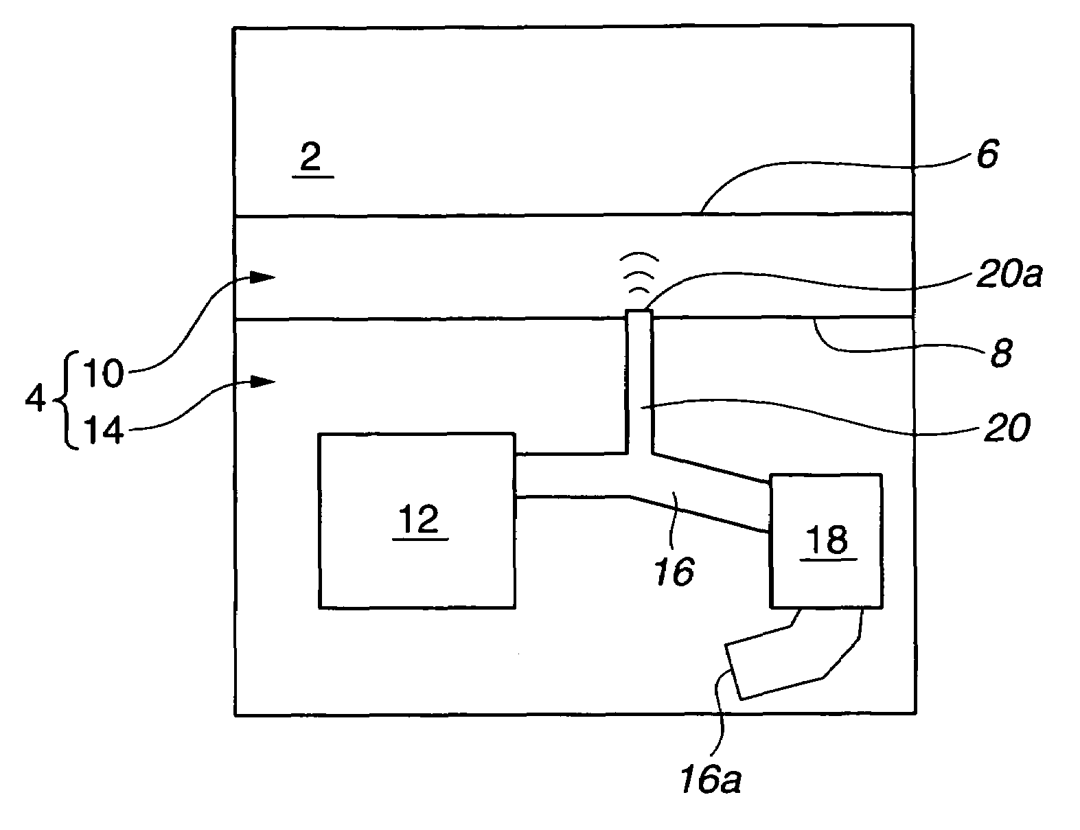
[0015]Embodiments of the present invention will be explained below with reference to the drawings. FIG. 1 shows a schematic system diagram of a A cabin 2 and an engine room 4 are partitioned by a dash panel 6. In engine room 4, a division wall or a partition wall 8 is provided on the side of dash panel 6. Then, a first engine room (or a first engine room space) 10 and a second engine room (or a second engine room space) 14 are defined by partition wall 8. First engine room 10 is located on the side of dash panel 6. In second engine room 14, an engine 12 is installed. As can be seen in FIG. 1, an engine inlet pipe 16 is provided for intake of air, and its one end is connected to engine 12. The other end of engine inlet pipe 16 is an open end (an air intake or an air inlet) 16a which opens for taking in outside air. Further, an air cleaner 18 is attached to engine inlet pipe 16 on the side of air inlet 16a. In addition, air cleaner 18 has a filtering portion (such as an air filter) f...
third embodiment
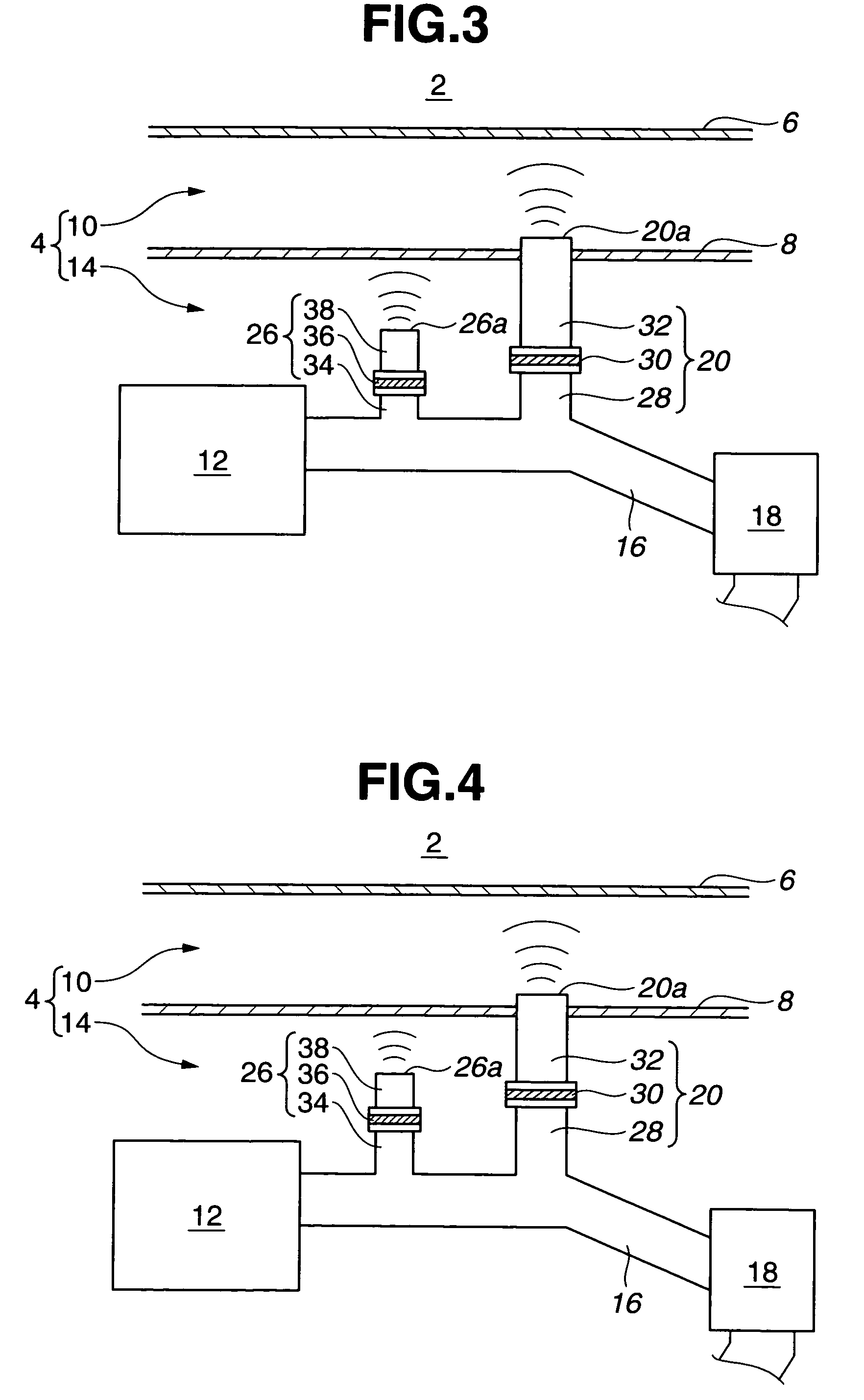
[0032]Accordingly, in the sound increase apparatus of the third embodiment, each of the intake sounds radiated from open end 20a of first addition pipe 32 and open end 26a of second addition pipe 38 is strengthened, and it is possible to render the sporty sound in the cabin.
second embodiment
[0033]In addition to this, in the same manner as the second embodiment, parts or components associated with respective routes where the respective intake sounds radiated from first addition pipe 32 and from second addition pipe 38 conveyed to cabin 2 are different from each other. Because of this, even if phases of the intake sounds radiated from first and second addition pipes 32 and 38 are opposite phases, these phases are respectively changed by the different routes or components while being conveyed to cabin 2. And therefore, a phase difference of these phases does not become 180 degrees (namely that these phases are not opposite phases) when the intake sounds are conveyed to cabin 2. It is therefore possible to prevent the level or volume of the intake sound conveyed inside cabin 2 from decreasing.
[0034]Further, in this embodiment, first communicating pipe 28 is set to be shorter than first addition pipe 32. Because of this, a resonance frequency of first communicating pipe 28 ...
PUM
 Abstract
Description
Claims
Application Information
 - R&D
- Intellectual Property
- Life Sciences
- Materials
- Tech Scout
- Unparalleled Data Quality
- Higher Quality Content
- 60% Fewer Hallucinations
Browse by: Latest US Patents, China's latest patents, Technical Efficacy Thesaurus, Application Domain, Technology Topic, Popular Technical Reports.
© 2025 PatSnap. All rights reserved.Legal|Privacy policy|Modern Slavery Act Transparency Statement|Sitemap|About US| Contact US: help@patsnap.com