Applicator, applicator cap and a container having an applicator cap

Inactive Publication Date: 2009-11-24
HENKEL IP & HOLDING GMBH
View PDF96 Cites 23 Cited by
  • Summary
  • Abstract
  • Description
  • Claims
  • Application Information

AI Technical Summary

Benefits of technology

[0050]In another construction the invention relates to an applicator comprising a stem with a first end for attachment to, or integrally formed with a cap, the stem having a free end comprising a flexible applicator element integrally formed with the stem, characterised in that the applicator element has at least one conduit running from the tip of the applicator element toward the stem, the conduit being dimensioned for uptake of liquid product by capillary action. This arrangement allows the uptake of product into specific regions of the applicator, and equally precise application of product from the uptake regions to the substrate.
[0051]The invention also relates to an applicator comprising a stem with a first end for attachment to, or integrally formed with a cap, the stem having a free end comprising a flexible applicator element integrally formed with the stem, characterised in that the applicator element is formed by a series of rods or ribs running lengthways along the applicator element to its tip, the rods or ribs being joined each to the next along their respective lengths by material of lesser thickness (and suitably planar) so that the rods project proud of opposing faces of the applicator element. Surfaces are thus provided on both side of the applicator element which allows retention of extra product.
[0052]In yet another embodiment the invention relates to an applicator comprising a stem with a first end for attachment to, or integrally formed with a cap, the stem having a free end comprising a flexible applicator element integrally formed with the stem, characterised in

Problems solved by technology

There are problems associated with various containers having applicator caps due to their particular construction.
The nature of the product contents of the container may also cause additional or exacerbate already existing problems with the applicator caps.
For instance the particular problem associated with curable compositions such as CA's is that the container must provide an environment as free as possible from environmental contamination.
Contamination of the product may cause premature curing so that the product becomes unusable.
Fouling of the cap and/or the applicator is also problematic with many products which dry or harden to a solid.
This is a re-occurring problem.
For instance, curable products, tend to adhere to the underside of the cap making it difficult to replace the cap so as to properly seal the container, thus exacerbating the problem.
This can adhere the cap to the container making manual removal of the cap difficult or even impossible so that the entire container may be discarded, even though it still contains otherwise useable product.
The product may also find its way into screw threads on the cap where it dries/hardens on the screw threads making removal and subsequent re-threading of the cap on the container difficult.
The selection of the material (usually a plastics material) is thus limited.
It has been found that in some instances adding colour to a natural plastic material contaminates CA produc

Method used


Image

  • Applicator, applicator cap and a container having an applicator cap
  • Applicator, applicator cap and a container having an applicator cap
  • Applicator, applicator cap and a container having an applicator cap

Examples


Embodiment Construction

[0115]The invention will now be described with reference to the accompanying drawings.

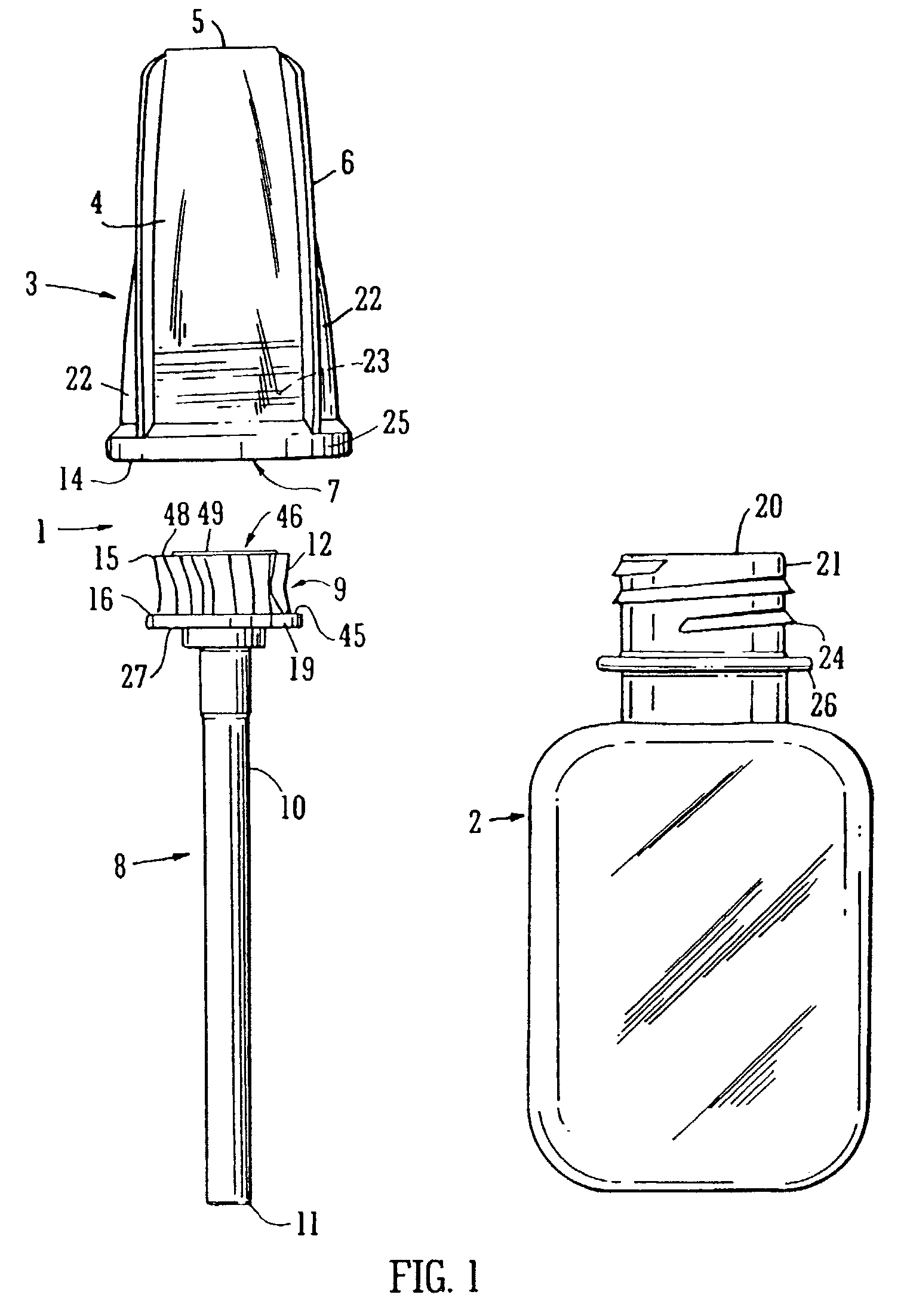
[0116]FIG. 1 shows an exploded view of an applicator cap 1 for use with a container 2.

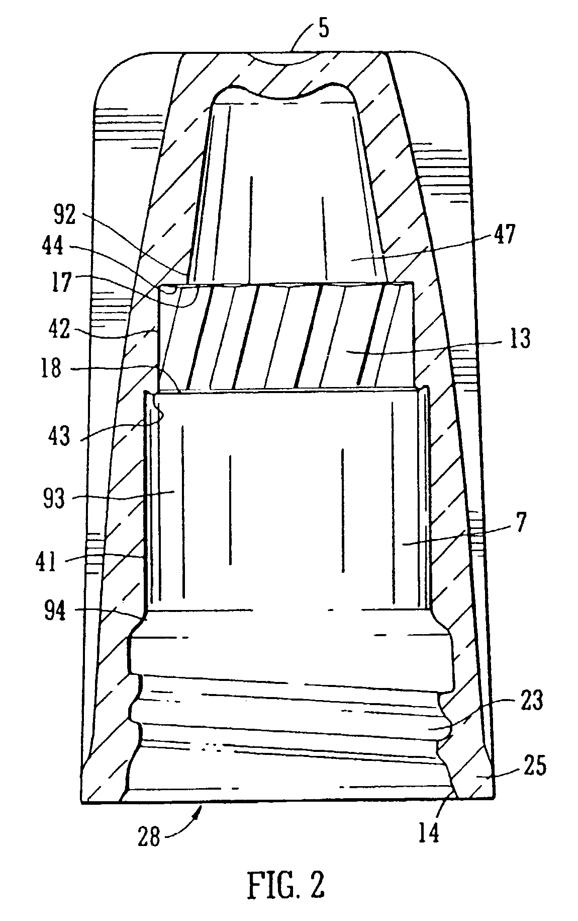
[0117]The applicator cap comprises an assembled arrangement of a cap 3 and applicator 8. The cap 3 comprises a cap body 4 with a top end in the form of a top wall 5 with an endless side wall 6 depending therefrom. The top wall 5 and the side wall 6 form a housing 7 for receiving a neck 14 of the container 2. The side wall 6 is generally in the form of the skirt creating the housing with circular cross section.

[0118]The applicator 8 has an applicator head 9 with an applicator stem 10 projecting from it. The applicator has a free end 11 for applying product from the container 2 to the desired surface on the substrate. In the embodiment shown the free end 11 is not adapted for any particular mode of application. The head 9 acts as a plug while the cap 3 acts a socket receiving the head 9 within the housing 7.

[0119]A ...


PUM


Abstract

A cap assembly for closing a container. The cap assembly has: (i) an undercap having a cap body with a top end (or wall) and with at least one endless side wall depending from the top end (or wall) to form a housing for receiving the neck of a container; (ii) an overcap having an overcap body with a top end and with at least one endless side wall depending from the top end to form a housing for receiving and engaging the (cap body of the) undercap; and (iii) an applicator having a stem with a first end for engagement with, or integrally formed with, the undercap within the housing, so that the stem projects from the housing, and a second free end for applying product. The exterior of the undercap body has a series of circumferentially arranged teeth for interengagement with a corresponding series of circumferentially arranged teeth within the housing of the overcap. The two series of teeth being interengageable at a number of relative positions, so that the relative orientation of the overcap to the undercap can be selected. As the undercap is adapted to be attached to the container, relative orientation of the overcap and the container is thus also selectable. In an alternative arrangement the two series of teeth form a safety or child proof cap arrangement. However, the application of a sufficient downward force upon the overcap causes the engagement of the two series of teeth allowing a user to rotate the overcap and undercap in unison. Biasing means may be provided to bias the overcap and undercap apart so that pressure must be applied against the biasing means to remove the cap assembly. Applicators are also provided as an assembly comprising an undercap and an applicator which can be assembled by screwing the undercap on a container into which the applicator has first been placed.

Description

FIELD OF THE INVENTION[0001]The invention relates to an applicator cap for applying a flowable product to a substrate and to containers for storing applicator dispensable products such as curable compositions for example cyanoacrylates (CA's), and indeed other products which dry or harden to a solid, for example correcting fluids and cosmetic compositions. The invention relates to an applicator cap assembly which is of simple construction yet reliable in use. The invention also relates to applicators and containers closed by applicator caps.BACKGROUND TO THE INVENTION[0002]Containers having associated applicator caps for dispensing materials held within the container are well known. Typically they comprise a cap / applicator assembly which is adapted to be threadibly received on a bottle. Usually, the applicator has a head which engages within a housing formed by the cap. However the applicator may be integrally formed with a cap, so that its stem projects from the cap. The applicator...

Claims


Application Information

Patent Timeline
IPC IPC(8): B65D47/04A46B11/00A47F5/00B43L19/00A45D34/04B05C17/00B65D41/04B65D50/04B65D77/30
CPCB65D41/0478B65D50/041B65D41/0485
Inventor DOHERTY, MICHAEL A.SEYMOUR, GEOFFREY F.
Owner HENKEL IP & HOLDING GMBH
Why Eureka
Try Eureka