Wire bonding method

a wire and wire technology, applied in the direction of soldering apparatus, manufacturing tools,auxillary welding devices, etc., can solve the problems of swelling and deterioration of achieve the effect of preventing swelling and improving the straightness of the wire loop

Inactive Publication Date: 2009-11-24
SHINKAWA CO LTD
View PDF6 Cites 128 Cited by
  • Summary
  • Abstract
  • Description
  • Claims
  • Application Information

AI Technical Summary

Benefits of technology

[0008]Accordingly, the object of the present invention is to provide a wire bonding method in which wire loop is prevented from swelling, thus improving the wire loop straightness.
[0025]As seen from the above, in the present invention, the capillary is, after the bonding at the first bonding point, moved in a direction away from the first bonding point, thus pulling the wire connected to the first bonding point and making it a linear wire portion, and then this linear wire portion is cut (separated) from the wire at the thin part. Thus, with this step, a spring-up part is formed in the wire bonded to the first bonding point and is then pulled and cut at the thin part to make a one-side supported linear wire portion, and the end of this one-side supported linear wire portion is pressed by the capillary and bonded to the external lead, wherefore wire loop straightness is enhanced.

Problems solved by technology

This hanging down part causes a repulsion to occur, when the wire is bonded at the second bonding point, so as to swell upward, resulting in that the straightness of the wire loop deteriorates.
Accordingly, the repulsion caused by plastic deformation of the hanging down part in the wire at the time of bonding at the second bonding point is not avoidable, and swelling occurs in the slanted part of the wire loop.

Method used


Image

  • Wire bonding method
  • Wire bonding method
  • Wire bonding method

Examples


Embodiment Construction

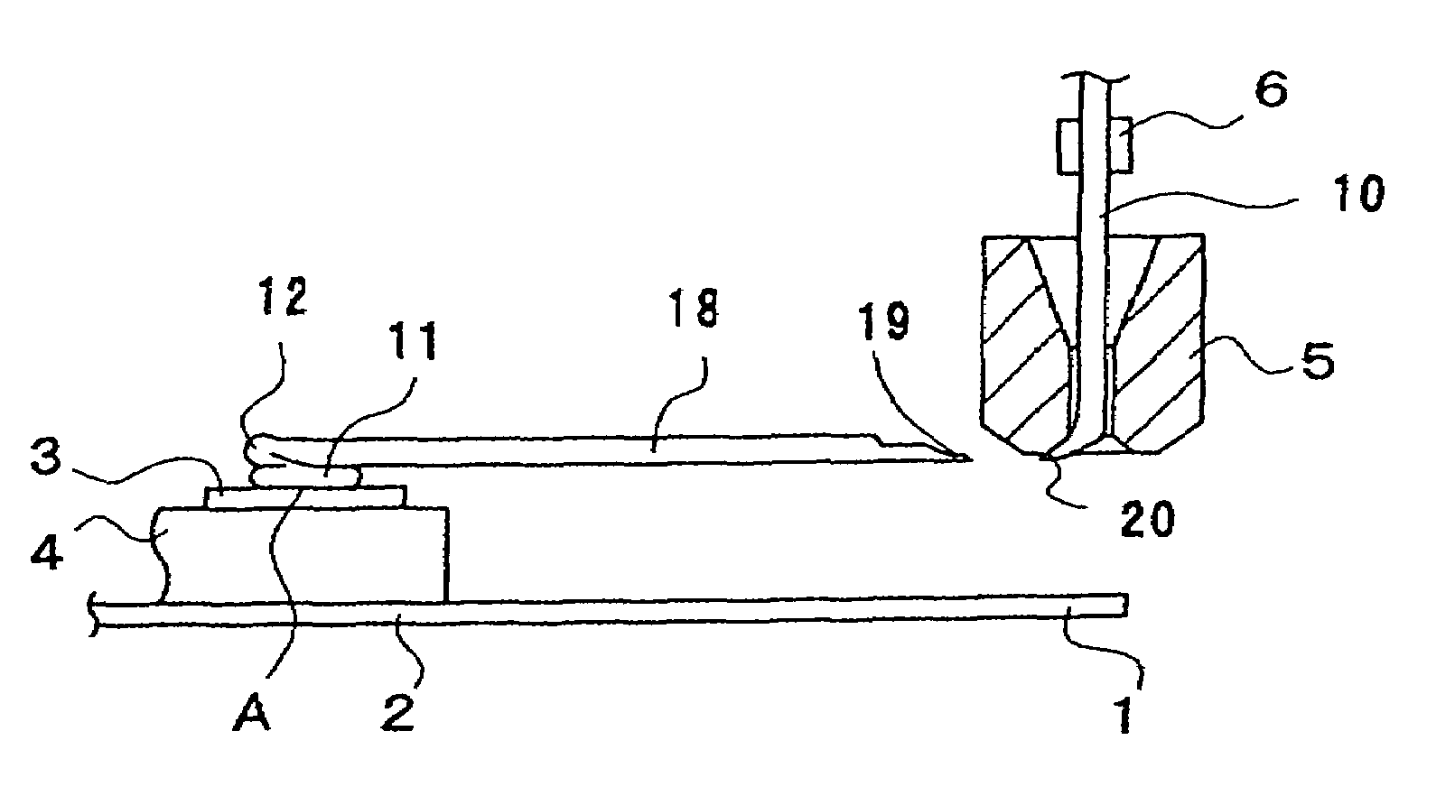
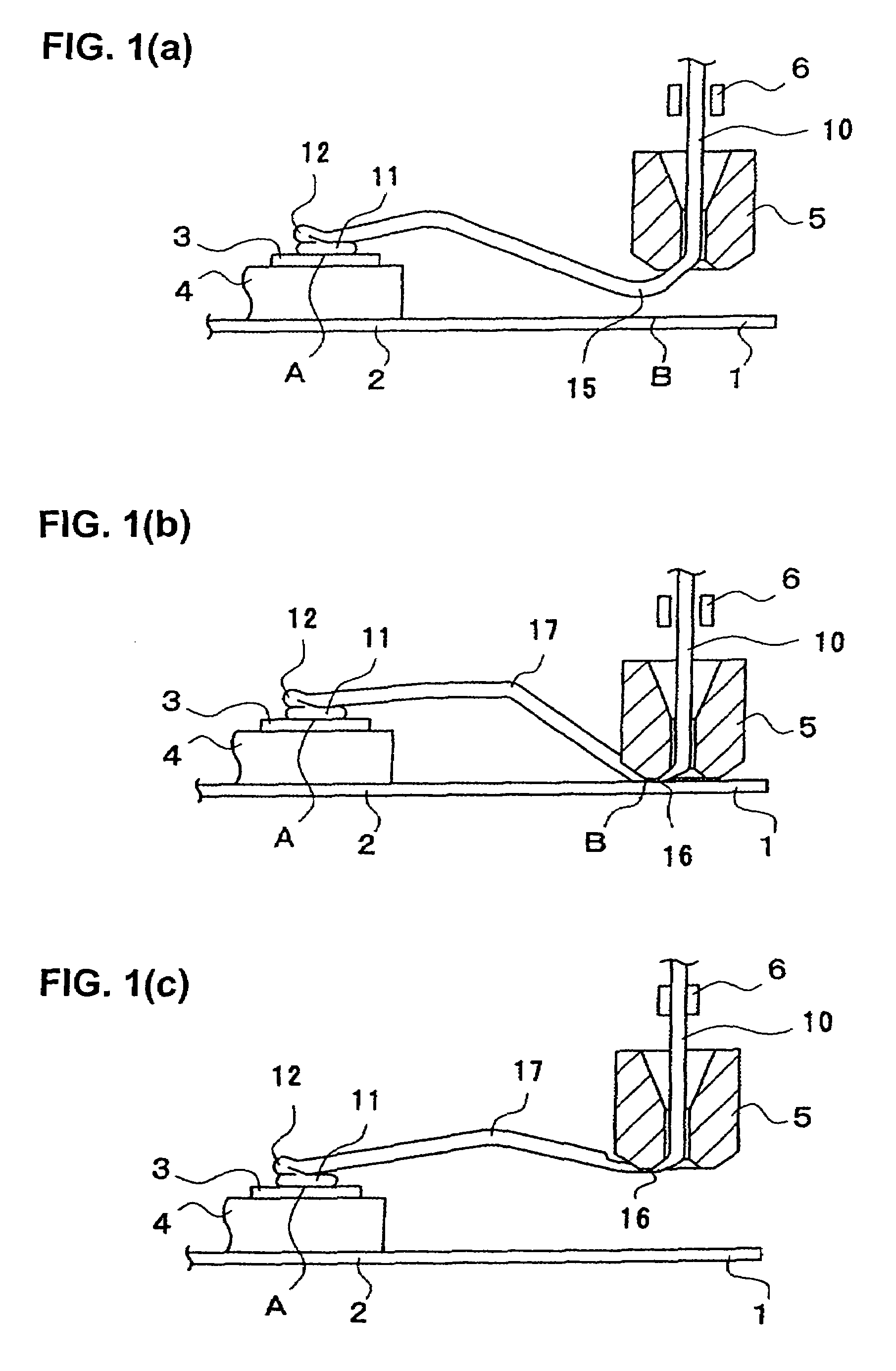
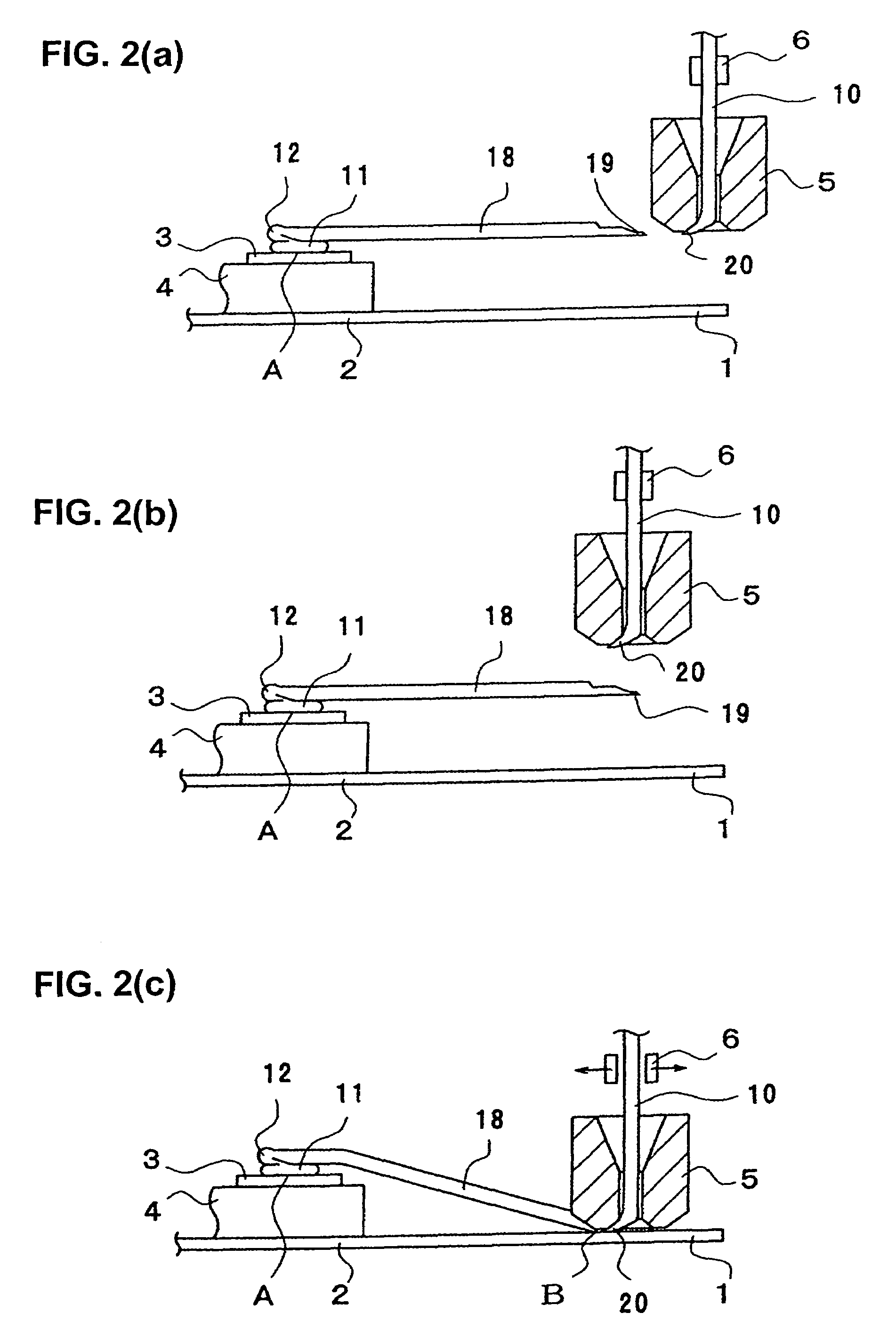
[0032]A first embodiment of the wire bonding method of the present invention will be described with reference to FIGS. 1(a) through 3(b).

[0033]On a lead frame 2 on which an external lead 1 is formed, a die 4 having thereon an electrode pad 3 is formed is mounted. As seen from FIG. 3(b), a wire 10 passes through a capillary 5. The reference numeral 6 indicates a clamper which makes the same horizontal and vertical motions as the capillary 5 whenever the capillary 5 is moved horizontally and vertically.

[0034]First of all, bonding is performed at the first bonding point A (first bonding) shown in FIG. 1(a), thus forming a pressure-bonded ball 11 and, on the pressure-bonded ball 11, a wire bonding part 12. The forming of this pressure-bonded ball 11 and wire bonding part 12 is effected by the method of, for instance, Japanese Patent Application Laid-Open Disclosure (1997) No. 9-51011. For more information on low height loop at the first bonding point, see JF'51011 which is incorporated ...


PUM

PropertyMeasurementUnit
pressureaaaaaaaaaa
heightaaaaaaaaaa
swellingaaaaaaaaaa

Abstract

A wire bonding method including the steps of: descending a capillary 5 from above an external lead 1 to press a wire 10 to such an extent that the wire is not completely connected to the external lead 1, thus forming a thin part 16 in the wire; next ascending the capillary 5 and the thin part 16 to substantially the same height as a first bonding point A, then moving the capillary 5 in a direction away from the first bonding point A, thus making a linear wire portion 18 and then cutting the wire at the thin part 16; then connecting the end 19 (thin part) of the linear wire portion 18 and the wire tip end 20 at the lower end of the capillary 5 are connected to the external lead 1; and then separating the wire tip end 20 from the external lead 1.

Description

BACKGROUND OF THE INVENTION[0001]The present invention relates to a wire bonding method for making connection between a die electrode pad and an external lead and more particularly to a method for forming low wire loop during wire bonding.[0002]In wire bonding, when, in order to bond a wire at a second bonding point, a capillary is moved to slightly above the second bonding point, excess wire hangs down from the lower end of the capillary, and a wire shape develops in which a hanging down part is formed. This hanging down part causes a repulsion to occur, when the wire is bonded at the second bonding point, so as to swell upward, resulting in that the straightness of the wire loop deteriorates. Japanese Patent Application Laid-Open Disclosure Nos. (1992) 4-370941 (Japanese Patent No. 3049515) and 2000-82717 disclose wire bonding methods for preventing wire loop from swelling at the time that bonding is made to the second bonding point.[0003]In the method of Japanese Patent Applicati...

Claims


Application Information

Patent Timeline
Patent Type & Authority Patents(United States)
IPC IPC(8): B23K31/00B23K31/02
CPCB23K20/004H01L24/85H01L24/48H01L2924/00014H01L24/78H01L2224/05599H01L2224/48091H01L2224/48227H01L2224/48465H01L2224/78301H01L2224/85181H01L2224/85399H01L2224/85951H01L2224/85986H01L2924/01004H01L2924/01005H01L2924/01082H01L2924/01006H01L2924/01033Y10S228/904H01L2224/48997H01L2224/45099H01L2924/00H01L2224/48455
Inventor MII, TATSUNARITOYAMA, TOSHIHIKOYOSHINO, HIROAKI
Owner SHINKAWA CO LTD
Why Eureka
Try Eureka