Brazed structural assembly and associated system and method for manufacture

a structural assembly and brazing technology, applied in the direction of manufacturing tools, transportation and packaging, and manufacturing tools, can solve the problems of material selection, material may not be optimal for elongation of the structural member, and the size, weight or other characteristics of the structural member are limited, so as to reduce time and energy, the effect of relatively fast and efficient performan

Inactive Publication Date: 2009-11-24
THE BOEING CO
View PDF37 Cites 4 Cited by
  • Summary
  • Abstract
  • Description
  • Claims
  • Application Information

AI Technical Summary

Benefits of technology

[0008]The braze joint can provide a metallurgical joint that is typically stronger and has better fatigue resistance that adhesive or press fitted joints. In addition, the electrical and thermal capabilities of such a brazed joint can be better than adhesive or press fit joints. That is, the brazed joint can perform better at high and low temperatures than non-metallurgical joints. Thus, the present invention provides a cap-braze-MMC-braze-cap product that is the functional equivalent or superior to conventional cap-MMC-cap products.
[0011]The members are typically formed with dimensions that are appropriate for carrying specific loads. The metal matrix composite material of the elongate member can provide a particular strength with a reduced mass relative to other materials, e.g., a thinner wall thickness in the case of a tubular member.
[0015]The brazing operation of the present invention can typically be performed relatively quickly and efficiently. In addition, the method can allow the use of connector members which are formed of materials that provide favorable wear characteristics but that may be difficult to join by other connection methods. Further, the joints can be formed by local heating, i.e., without heating the entire elongate member, thereby potentially reducing the time and energy required.

Problems solved by technology

For some structural members, the choice of material is limited by the required properties.
However, in many cases, the size, weight, or other characteristics of the structural member are limited by the application.
Nevertheless, the material may be less than optimal for use in the elongate member.
However, if the same composite material does not provide the necessary characteristics for use in the connection portions, the composite material may be unsuitable for the structural member.
Further, forming composite materials to a more complicated geometry, as is often required for the connection portions, can significantly increase the time and / or cost for manufacture.

Method used


Image

  • Brazed structural assembly and associated system and method for manufacture
  • Brazed structural assembly and associated system and method for manufacture
  • Brazed structural assembly and associated system and method for manufacture

Examples


Embodiment Construction

[0025]The present invention now will be described more fully with reference to the accompanying drawings, in which some, but not all embodiments of the invention are shown. This invention may be embodied in many different forms and should not be construed as limited to the embodiments set forth; rather, these embodiments are provided so that this disclosure will be thorough and complete, and will fully convey the scope of the invention to those skilled in the art. Like numbers refer to like elements throughout.

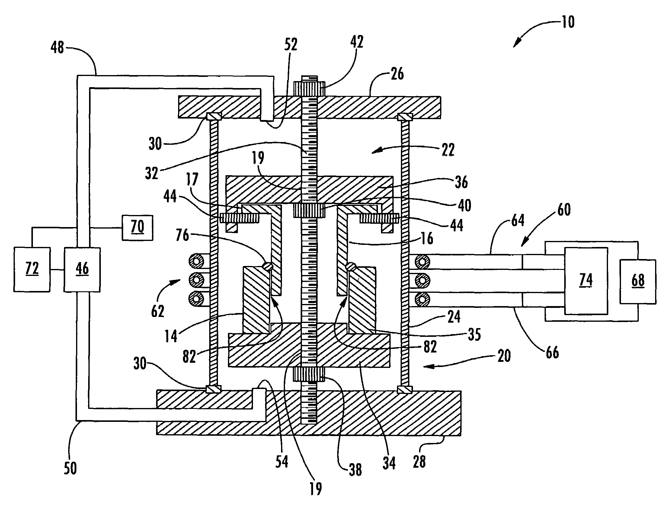
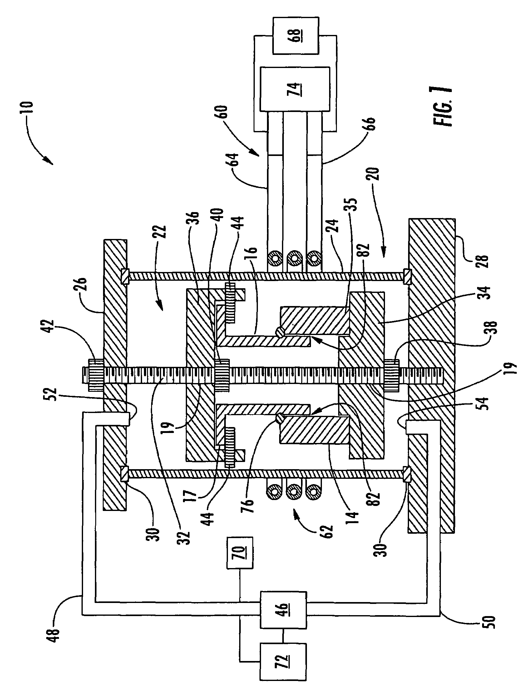
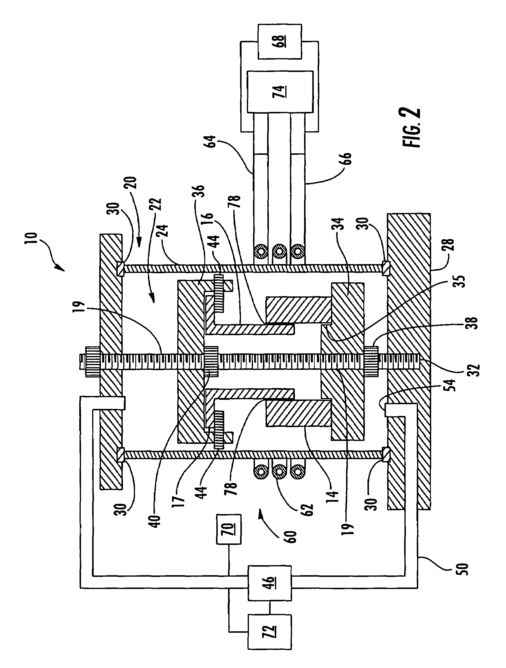
[0026]Referring now to the drawings, and in particular to FIGS. 1 and 5, a system 10 for joining structural members to form a structural assembly 12 typically includes an elongate member (an arm) 14 and connectors 16, 18 at its ends. Structural assemblies of various configurations can be formed according to the present invention. Typically, the structural assembly includes an elongate member and at least one connector member. For example, FIG. 5 illustrates a structural assemb...


PUM

PropertyMeasurementUnit
ultimate tensile strengthaaaaaaaaaa
melting temperatureaaaaaaaaaa

Abstract

A structural assembly and an associated system and method for manufacture are provided. The structural assembly includes an elongate member and a first connector member that is connected to an end of the elongate member by a braze joint. A second connector member can be connected to an end of the elongate member opposite the first connector by another braze joint. The elongate member is formed of a metal matrix composite material that includes a plurality of fibers of a reinforcement material disposed in a metal matrix. Each connector member is formed of a material that is dissimilar to the material of the elongate member. The braze joints can be formed by selectively heating the braze material, e.g., with an inductive coil that extends circumferentially around only a portion of the structural assembly.

Description

BACKGROUND OF THE INVENTION[0001]1. Field of the Invention[0002]The present invention relates to the joining of structural members and, more particularly, relates to the brazing of structural members to form a structural assembly such as an elongate member joined with at least one connector.[0003]2. Description of Related Art[0004]The selection of material for forming a structural member is typically based, at least in part, on the material's properties such as strength, stiffness, toughness, corrosion resistance, and the like. For some structural members, the choice of material is limited by the required properties. For example, braces, struts, connecting rods, and the like are typically elongate, rod- or beam-like components that define connection portions at the opposite ends. The elongate portion of such a structural member generally requires high axial strength so that the member can transmit loads between the opposite ends. Each of the connection portions at the ends of the me...

Claims


Application Information

Patent Timeline
Patent Type & Authority Patents(United States)
IPC IPC(8): B23K1/002B23K1/00B23K3/00
CPCB64C1/06Y02T50/433B64C2001/0081B64C2001/0072Y02T50/40
Inventor NANSEN, DAVID S.MATSEN, MARC R.SMITH, TERRY L.HERB, WILLIAM R.BROWN, RONALD W.FIRTH, LEE C.
Owner THE BOEING CO
Why Eureka
Try Eureka