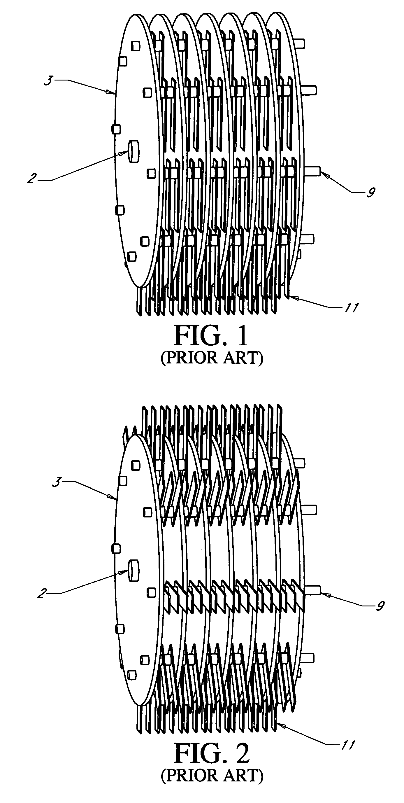
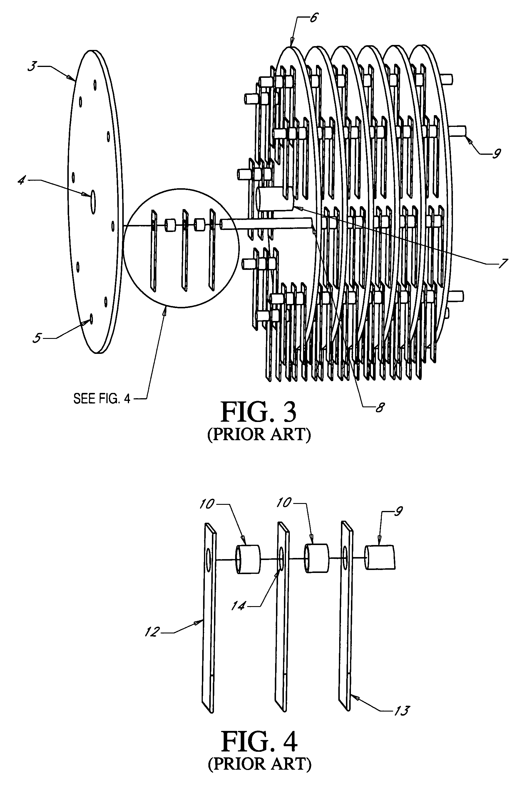
Hammermill hammer

a hammer and hammer rod technology, applied in the field of hammer mill hammer, can solve the problems of deterioration of the roundness of the rod hole, catastrophic failure or loss of performance, elongation of the hammer rod hole, etc., and achieve the effect of improving efficiency and improving efficiency

Active Publication Date: 2009-11-24
GENESIS III
View PDF33 Cites 39 Cited by
  • Summary
  • Abstract
  • Description
  • Claims
  • Application Information

AI Technical Summary

Benefits of technology

[0011]The methods and apparatus disclosed herein may be applied to a single hammer or multiple hammers to be installed in a hammermill. The hammer may be produced through forging, casting or rolling as found in the prior art. Applicant has previously taught that forging the hammer improves the characteristic of hardness for the hammer body. Applicant has also taught the thickness of the hammer edge, in relation to the hammer neck, may also be increased. Re-distributing material (and thus weight) from the hammer neck back to the hammer edge, to increase the moment produced by the hammer upon rotation while allowing the overall weight of the hammer to remain relatively constant. Applicant's present design may be combined with previous teachings related to the shape of the hammer and the methods of producing the hammer. Thus, the present design may enjoy an increase in actual hammer momentum available for comminution developed and delivered through rotation of the hammer than the hammers as found in the prior art. This increased momentum reduces recoil, as previously disclosed and claimed, thereby increasing operational efficiency. However, because the hammer design is still free swinging, the hammers can still recoil, if necessary, to protect the hammermill from destruction or degradation if a non-destructible foreign object has entered the mill. Thus, effective horsepower requirements are held constant, for similar production levels, while actual strength, force delivery and the area of the screen covered by the hammer face within the hammermill, per each revolution of the hammermill rotor, are improved. The overall capacity of a hammermill employing the various hammers embodied herein is increased over existing hammers.
[0023]It is another object of the present invention to disclose and claim a hammer design that allows for improved efficiency by increasing the hammer contact surface area.

Problems solved by technology

However, because the hammer design is still free swinging, the hammers can still recoil, if necessary, to protect the hammermill from destruction or degradation if a non-destructible foreign object has entered the mill.
In the prior art, the roundness of the rod hole deteriorates leading to elongation of the hammer rod hole.
Elongation eventually translates into the entire hammer mill becoming out of balance or the individual hammer breaking at the weakened hammer rod hole area which can cause a catastrophic failure or a loss of performance.
When a catastrophic failure occurs, the hammer or rod breaking can result in metallic material entering the committed product requiring disposal.
This result can be very expensive to large processors of metal sensitive products i.e. grain processors.
Additionally, catastrophic failure of the hammer rod hole can cause the entire hammermill assembly to shift out of balance producing a failure of the main bearings and or severe damage to the hammermill itself.

Method used


Image

  • Hammermill hammer
  • Hammermill hammer
  • Hammermill hammer

Examples


first embodiment

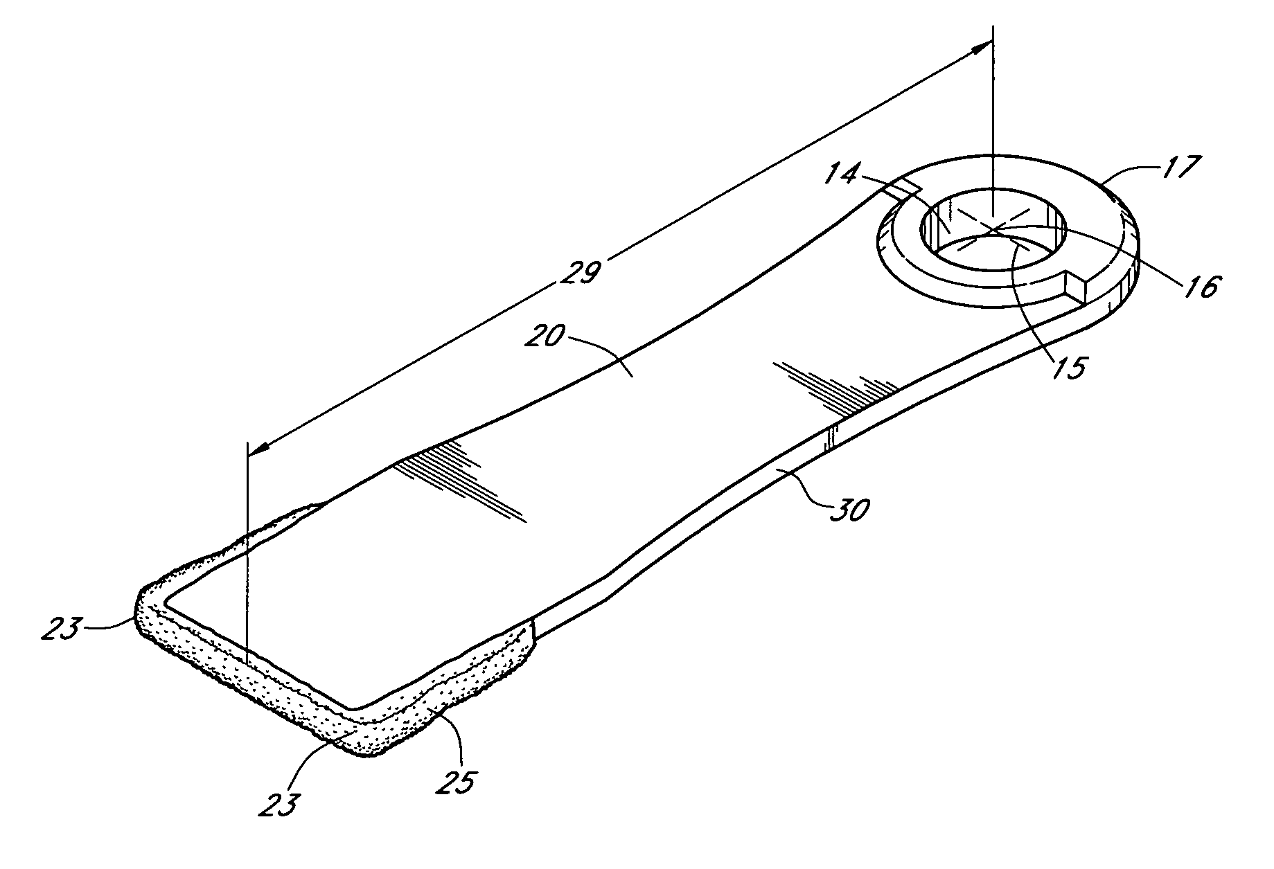
[0072]FIGS. 5-7 show the present invention, particularly hammers to be installed in the hammermill assembly. FIG. 5 presents a perspective view of this embodiment of the improved hammer 11. As shown, the first end of the hammer 17 is for securement of the invention within the hammermill assembly 1 (not shown) by insertion of the hammer rod 9 through hammer rod hole 14 of the hammer 11. In FIG. 5 the center of the rod hole 16 is highlighted. The distance from the center of rod hole 16 to the contact or second end of the hammer 23 is defined as the hammer swing length 29. Typically, the hammer swing length 29 of the present embodiment is in the range of eight (8) to ten (10) inches with most applications measuring eight and five thirty seconds inches (8 5 / 32″) to nine and five thirty seconds (9 5 / 32″).

[0073]In the embodiment of the hammer 11 shown in FIGS. 5-7, the hammer rod hole 14 is surrounded by a single stage hammer rod hole shoulder 27. In this embodiment, the hammer shoulder 2...

second embodiment

[0077]FIG. 8 best illustrates the curved, rounded nature of the present invention, as shown by the arcuate edges from the first end of the hammer 17 and continuing through hammer neck 20 to the second hammer end 23. To further reduce hammer weight, hammer neck holes 22 have been placed in the hammer neck 20. The hammer neck holes 22 may be asymmetrical as shown or symmetrical to balance the hammer 11. The arcuate, circular or bowed nature of the hammer neck holes 22 as shown allows transmission and dissipation of the stresses produced at the first end of the hammer 17 through and along the neck of the hammer 20.

[0078]As emphasized and illustrated by FIGS. 8 and 10, the reduction in hammer neck thickness and weight allowed through both the combination of the hammer neck shape and hammer neck holes 22 provide improved hammer neck strength at reduced weight therein allowing increased thickness at the first and second ends of the hammer, 17 and 23, respectively, to improve both the secu...

third embodiment

[0080]FIG. 11 illustrates the curved hammer neck edges 30 which give the hammer 11 an hourglass shape starting below the hammer rod hole 14 and at the first end of the hammer 17 and continuing through the hammer neck 20 to the second end of the hammer 23. Incorporation of this shape into the present invention assists with hammer weight reduction while also reducing the vibration of the hammer 11 as it rotates in the hammer mill and absorbs the shock of contact with comminution materials.

[0081]As shown and illustrated by FIG. 13 which provides a side view of the present embodiment, the first end of the hammer 17, the neck 20 and the second end of the hammer 23 are of a substantially similar thickness with the exception of the stage 1 and 2 hammer rod hole reinforcement shoulders, 27 and 28, to maintain the hammer's reduced weight over the present art. As emphasized and further illustrated by FIGS. 11-13, the reduction in the hammer profile and weight allowed through both the combinat...


PUM


Abstract

An improved free swinging hammer mill hammer design is disclosed and described for comminution of materials such as grain and refuse. The hammer design of the present art is adaptable to most hammer mill or grinders having free swinging systems. The improved hammermill hammer may incorporate multiple comminution edges for increased comminution efficiencies. The design as disclosed and claimed may be forged to increase the strength of the hammer. A rod hole shoulder surrounding a portion of the rod hole adjacent the neck may be reduced in the radial dimension. The shape of the hammer body may be varied, as disclosed and claimed, to further improve hammer strength, or reduce or maintain the weight of the hammer while increasing the amount of force delivered to the material to be comminuted.

Description

CROSS REFERENCE TO RELATED APPLICATIONS[0001]This patent application is a continuation-in-part of U.S. patent application Ser. No. 11,544,526 previously filed on Oct. 6, 2006 now U.S. Pat. No. 7,559,497 which was a continuation-in-part of patent application Ser. No. 11,150,430, previously filed on Jun. 11, 2005, now U.S. Pat. No. 7,140,569. Applicant herein claims priority from and incorporates herein by reference in its entirety the preceding referenced applications.STATEMENT REGARDING FEDERALLY SPONSORED RESEARCH OR DEVELOPMENT[0002]No federal funds were used to develop or create the invention disclosed and described in the patent application.REFERENCE TO SEQUENCE LISTING, A TABLE, OR A COMPUTER PROGRAM LISTING COMPACT DISK APPENDIX[0003]Not ApplicableBACKGROUND OF THE INVENTION[0004]A number of different industries rely on impact grinders or hammermills to reduce materials to a smaller size. For example, hammermills are often used to process forestry and agricultural products as ...

Claims


Application Information

Patent Timeline
Patent Type & Authority Patents(United States)
IPC IPC(8): B02C13/28
CPCB02C13/28
Inventor YOUNG, ROGER T.
Owner GENESIS III
Why Eureka
Try Eureka