Intervertebral space implant for use in spinal fusion procedures

a technology for intervertebral space and spinal fusion, which is applied in the field of implants, can solve the problems of insufficient amount of spreading of vertebrae with posterior implants, insufficient size implants, and nerve injury or scarring, and achieves maximum flexibility in positioning, minimal risk of damage to sensitive surrounding tissues, and maximum size of intervertebral space

Inactive Publication Date: 2009-11-24
DEPUY ACROMED INC +1
View PDF27 Cites 40 Cited by
  • Summary
  • Abstract
  • Description
  • Claims
  • Application Information

AI Technical Summary

Benefits of technology

[0019]Another object of the present invention is to provide an intervertebral space implant assembly which can be adjusted in height to maximize a size of the intervertebral space generally and to allow for selective height adjustment within different portions of the intervertebral space, to provide a surgeon

Problems solved by technology

Direct posterior access to the intervertebral space requires moving the spinal nerves within the spinal canal towards the midline and can result in nerve injury or scarring.
Additionally, implants of a smaller size are typically required due to the small amount of clearance between vertebral structures.
Hence, the amount of spreading of the vertebrae with a posterior implant is often less than a

Method used


Image

  • Intervertebral space implant for use in spinal fusion procedures
  • Intervertebral space implant for use in spinal fusion procedures
  • Intervertebral space implant for use in spinal fusion procedures

Examples


Embodiment Construction

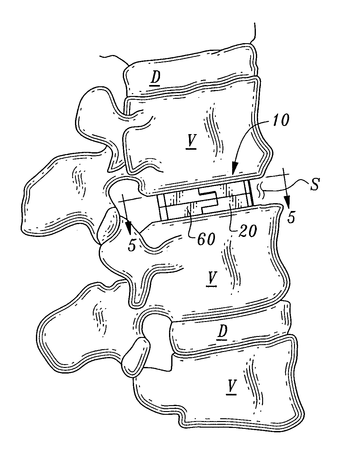
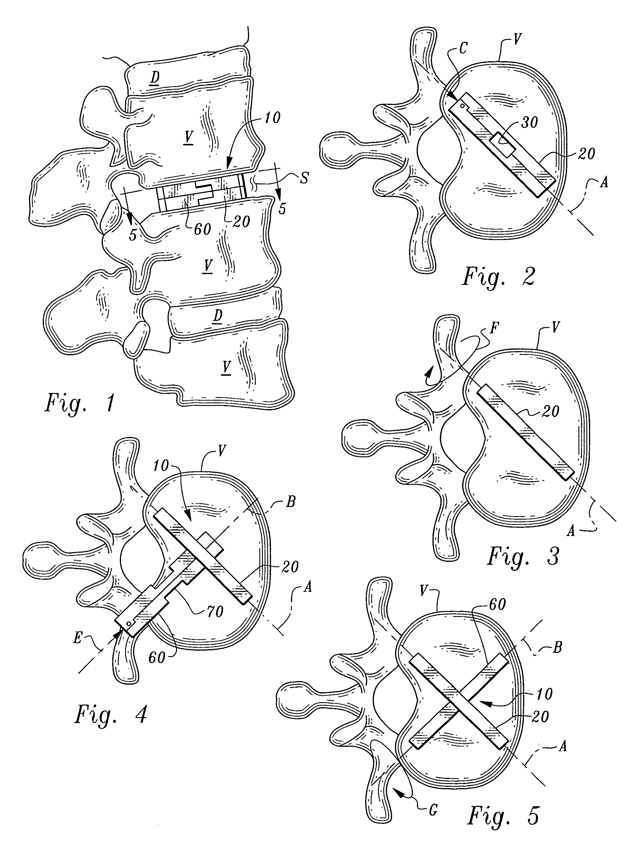
[0044]Referring to the drawings, wherein like reference numerals represent like parts throughout the various drawing figures, reference numeral 10 (FIG. 1) is directed to an implant assembly for implantation into an intervertebral space S between adjacent vertebrae V after a disk D has been removed from the intervertebral space S. A primary segment 20 and a secondary segment 60 are implanted along separate pathways but interlock together within the intervertebral space S to form a single implant assembly 10. The resulting assembly 10 securely stabilizes the vertebrae V adjacent the intervertebral space S for spinal fusion of the vertebrae V together.

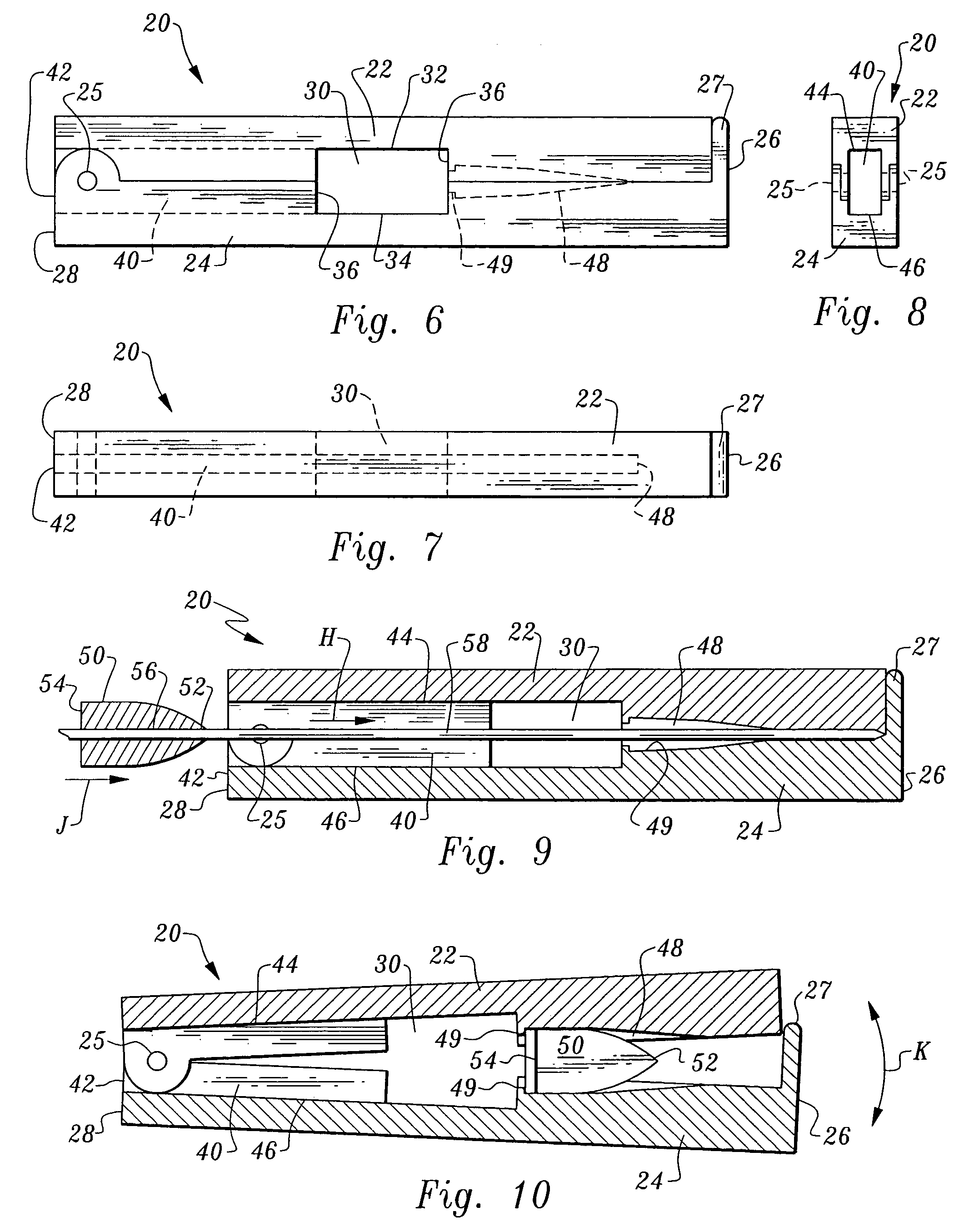
[0045]In essence, and with particular reference to FIGS. 1-5, the basic details of the implant assembly 10 are described. The implant assembly 10 includes a primary segment 20 (FIG. 2) and a secondary segment 60 (FIG. 4). The primary segment 20 is elongate in form extending along a primary axis A. The primary segment 20 is preferably hig...


PUM


Abstract

An implant assembly is provided for surgical implantation into an intervertebral space, such as for stabilization of vertebrae adjacent the intervertebral space during a spinal fusion procedure. The implant assembly includes a primary segment separate from a secondary segment. These segments are elongate and of sufficiently small cross-section that they can be implanted posteriorly in a minimally invasive manner. The primary segment preferably includes a tunnel and the secondary segment preferably includes a neck with the tunnel and neck sized complementally so that the segments stabilize each other where they intersect with the neck within the tunnel. The entire implant assembly is thus provided which both widens and supports the intervertebral space and is sufficiently rigid to provide adequate support for the intervertebral space as the vertebrae are fusing together.

Description

CROSS-REFERENCE TO RELATED APPLICATIONS[0001]This application is a continuation of International Patent Application No. PCT / US02 / 08845 filed on Mar. 22, 2002 with a priority date of Mar. 27, 2001 corresponding with Priority application Ser. No. 09 / 819,461, now U.S. Pat. No. 6,368,351.FIELD OF THE INVENTION[0002]The following invention relates to implants which are configured to be placed within an intervertebral space between adjacent spinal vertebrae after a disk has been removed from the space and to facilitate fusion of the vertebrae together. More particularly, this invention relates to implants which can be implanted posteriorly in either a minimally invasive or open manner and spread vertebrae adjacent the intervertebral space away from each other to recreate the lumbar lordosis and support the vertebrae while they fuse together.BACKGROUND OF THE INVENTION[0003]Spinal fusion procedures are known as an effective treatment for certain spinal conditions. In general, such spinal f...

Claims


Application Information

Patent Timeline
IPC IPC(8): A61F2/44A61F2/00A61F2/02A61F2/30A61F2/46
CPCA61F2/4611A61F2/4455A61F2/442Y10S606/91A61F2002/30153A61F2002/30179A61F2002/30331A61F2002/30507A61F2002/30523A61F2002/30538A61F2002/30556A61F2002/30604A61F2002/30626A61F2002/30975A61F2002/4622A61F2002/4628A61F2220/0025A61F2220/0033A61F2230/0019A61F2250/0006A61F2250/0009A61F2310/00017A61F2002/30624A61F2/44
Inventor GLENN, BRADLEY J.SCHNEIDERMAN, GARY A.
Owner DEPUY ACROMED INC
Why Eureka
Try Eureka