Vibration correcting device, lens barrel, and optical device

a vibration correction and lens barrel technology, applied in the field of image vibration correction devices, can solve the problems of harmfully affecting the drive of the shift member, difficult to reduce the rigidity of the flexible substrate, and difficult to reduce the elastic force in the optical axis direction to be generated on the flexible substrate to a permissible level, so as to reduce the frictional force of the drive, prevent the influence of the elastic force in the optical axis direction of the flexible substrate, and improve the effect of optical performan

a vibration correction and lens barrel technology, applied in the field of image vibration correction devices, can solve the problems of harmfully affecting the drive of the shift member, difficult to reduce the rigidity of the flexible substrate, and difficult to reduce the elastic force in the optical axis direction to be generated on the flexible substrate to a permissible level, so as to reduce the frictional force of the drive, prevent the influence of the elastic force in the optical axis direction of the flexible substrate, and improve the effect of optical performan

US7623151B2Inactive Publication Date: 2009-11-24CANON KK

Image

  • Vibration correcting device, lens barrel, and optical device
  • Vibration correcting device, lens barrel, and optical device
  • Vibration correcting device, lens barrel, and optical device

Examples


Embodiment Construction

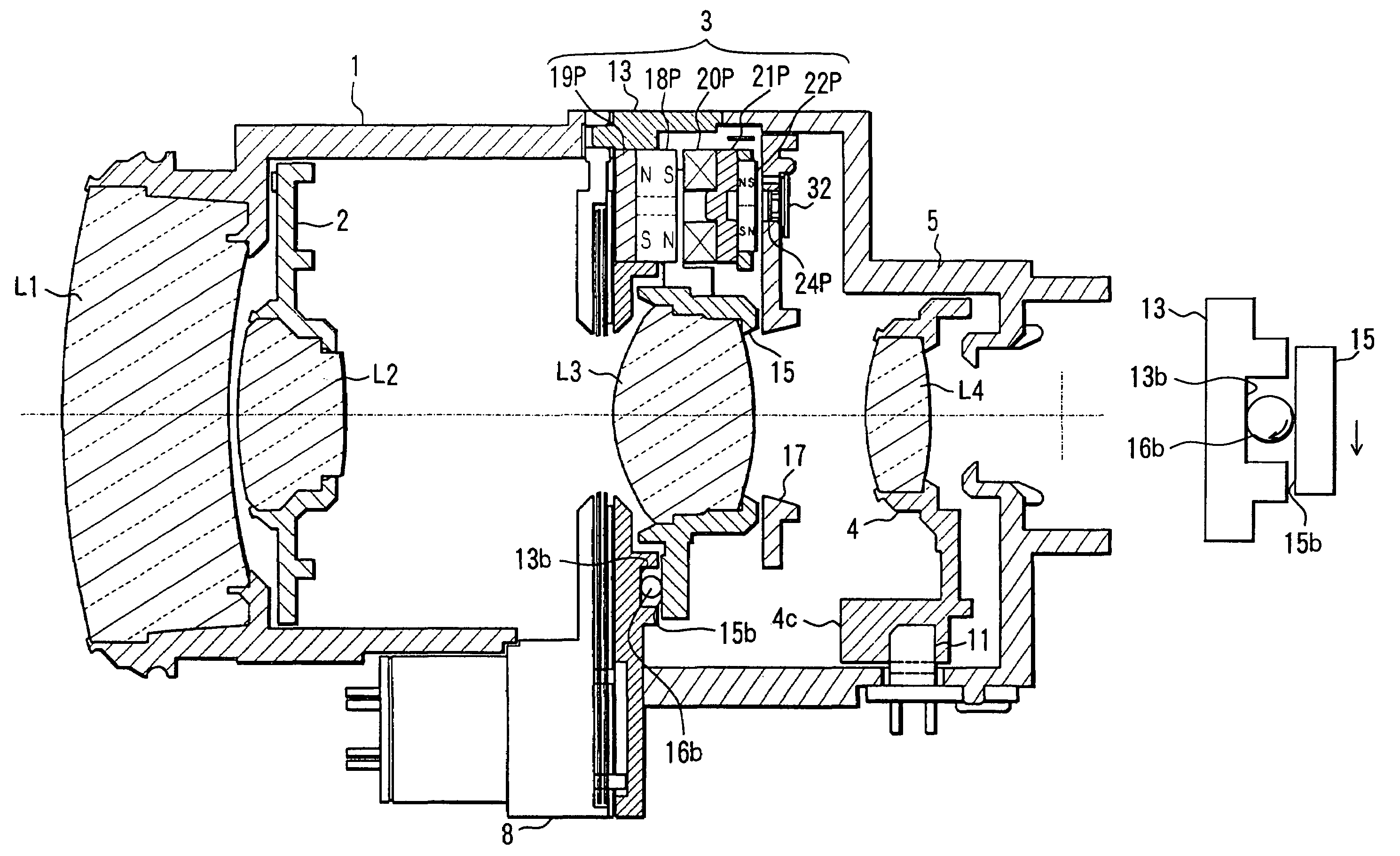
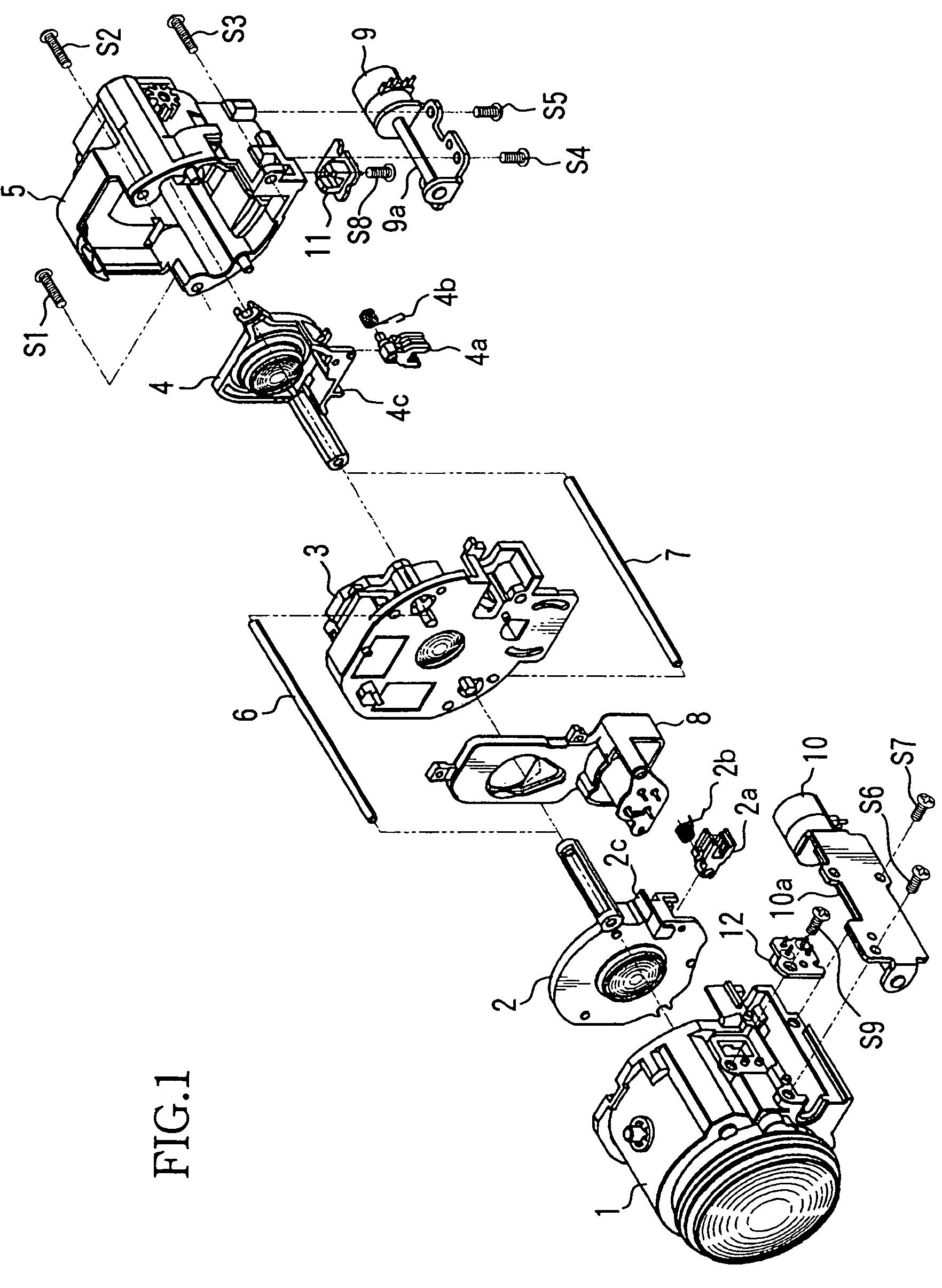
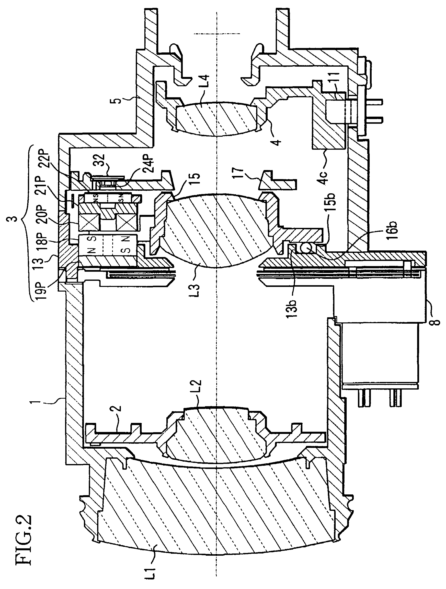
[0116]FIG. 1 and FIG. 2 show the construction of a lens barrel with a vibration correcting device of an embodiment of the invention. FIG. 1 shows the exploded perspective view of the lens barrel, and FIG. 2 shows the sectional view of the lens barrel. This lens barrel is used for a shooting device such as a video camera.

[0117]The optical system of this lens barrel is a zooming optical system composed of four groups, that is, a positive lens component, negative lens component, positive lens component, and positive lens component in order from the subject or observing object side.

[0118]L1 shows a fixed first lens group, L2 shows a second lens group which moves in the optical axis direction to carry out zooming operation, L3 shows a third lens group (vibration correcting lens: hereinafter referred to as shift lens) which moves within the optical axis orthogonal plane to carry out vibration correcting operation, and L4 shows a fourth lens group which moves in the optical axis direction ...


PUM


Abstract

An optical device with an imaging device for forming an image of a subject with a lens device includes a lens unit, a movable member making the lens unit movable within a plane orthogonal to the optical axis of the lens unit, an image pickup device imaging the subject image formed by the lens device, a fixed member limiting the movement of the movable member in the optical axis direction, at least three balls rolling between the movable and fixed member, a vibration detecting unit, and pitch and yaw direction drive units for driving the movable member in the pitch and yaw directions within the optical axis orthogonal plane, respectively. The pitch and yaw direction drive units press the movable member toward the fixed member side by means of magnetic pressing forces caused by magnetic attractive action between drive magnets and yokes.

Description

CROSS-REFERENCE TO RELATED APPLICATION[0001]This application is a divisional application of application Ser. No. 10 / 021,045 filed Dec. 19, 2001, pending.BACKGROUND OF THE INVENTION[0002]1. Field of the Invention[0003]The present invention relates to an image vibration correcting device for shifting a lens within an optical axis orthogonal plane to correct image vibration due to so-called hand movements, and for example, a vibration correcting device suitable for being installed in a lens barrel, or a imaging[0004]device such as a video camera, digital still camera or the like, or an observation device such as binoculars, astronomical telescope or the like.[0005]2. Description of the Related Art[0006]In order to prevent image vibration due to hand movements or the like which is easily caused when shooting in a hand-held condition, various devices have been proposed for realizing vibration correction by detecting vibration information of a camera or binoculars and optically canceling ...

Claims


Application Information

Patent Timeline
24 Nov 2009
Publication
US7623151B2
IPC
H04N5/228; H04N23/40; G03B5/00
CPC
G03B5/00; H04N5/23248; G02B27/646; H04N5/23287; H04N5/23258; G03B2217/005; G03B2205/0015; G03B2205/0069
Inventors
NOGUCHI, KAZUHIRO