Apparatus and method for the automated marking of defects on webs of material

a technology of automatic marking and defects, applied in the direction of material analysis, instruments, textiles and paper, etc., can solve the problems of insufficient edge marking of webs, difficult to accurately identify defective areas, and insufficient marking of web edges

Active Publication Date: 2009-11-24
3M INNOVATIVE PROPERTIES CO
View PDF117 Cites 22 Cited by
  • Summary
  • Abstract
  • Description
  • Claims
  • Application Information

AI Technical Summary

Benefits of technology

[0008]The present invention provides a system for the characterization of webs that permits the identification of anomalous regions on the web to be performed at a first time and place, and permits the localization and marking of actual defects to be performed at a second time and place. This allows the selection of what constitutes an actual defect with respect to the contemplated end-use of the web to be made “just-in-time”. Material waste is reduced since the criteria of what constitutes defects that would disqualify a portion of the web for a particular end use no longer needs to be equivalent to that used for the most demanding end-use applications.
[0016]Following the guidance of the just mentioned reference, it will frequently be advantageous to perform a storing or buffering of the identified regions prior to analyzing them, even to such an extent that the stored or buffered information is analyzed after the imaging has been performed on the entire web. When it is convenient for the user of the method to perform the identification of anomalous regions on the web at a first time and place and perform the localization and marking of actual defects at a second time and place, it will usually also be convenient to perform a winding of the web onto a roll between the placing step and the applying step. The wound roll can then be shipped to a convenient place along with the stored information about its surface anomalies, where it can there wait for a decision to be made about application of the roll to a specific end-use. Depending on the exact end-use, it may be convenient to place the locating marks on or adjacent to the anomalies whose position they identify, or it may be convenient to place the locating marks such that they are spaced in a predetermined way from the anomalies whose position they identify.

Problems solved by technology

Unfortunately, accurate identification of defective areas can be extremely difficult depending on the nature of the web combined with the time and place of product converting.
Unfortunately, there are more situations arising where edge marking of webs is not sufficient.
1) Defects difficult to later identify such that even with the presence of an edge mark humans may have a very difficult time finding the defect.
Wide webs and small defects compound this situation.

Method used


Image

  • Apparatus and method for the automated marking of defects on webs of material
  • Apparatus and method for the automated marking of defects on webs of material
  • Apparatus and method for the automated marking of defects on webs of material

Examples


example 1

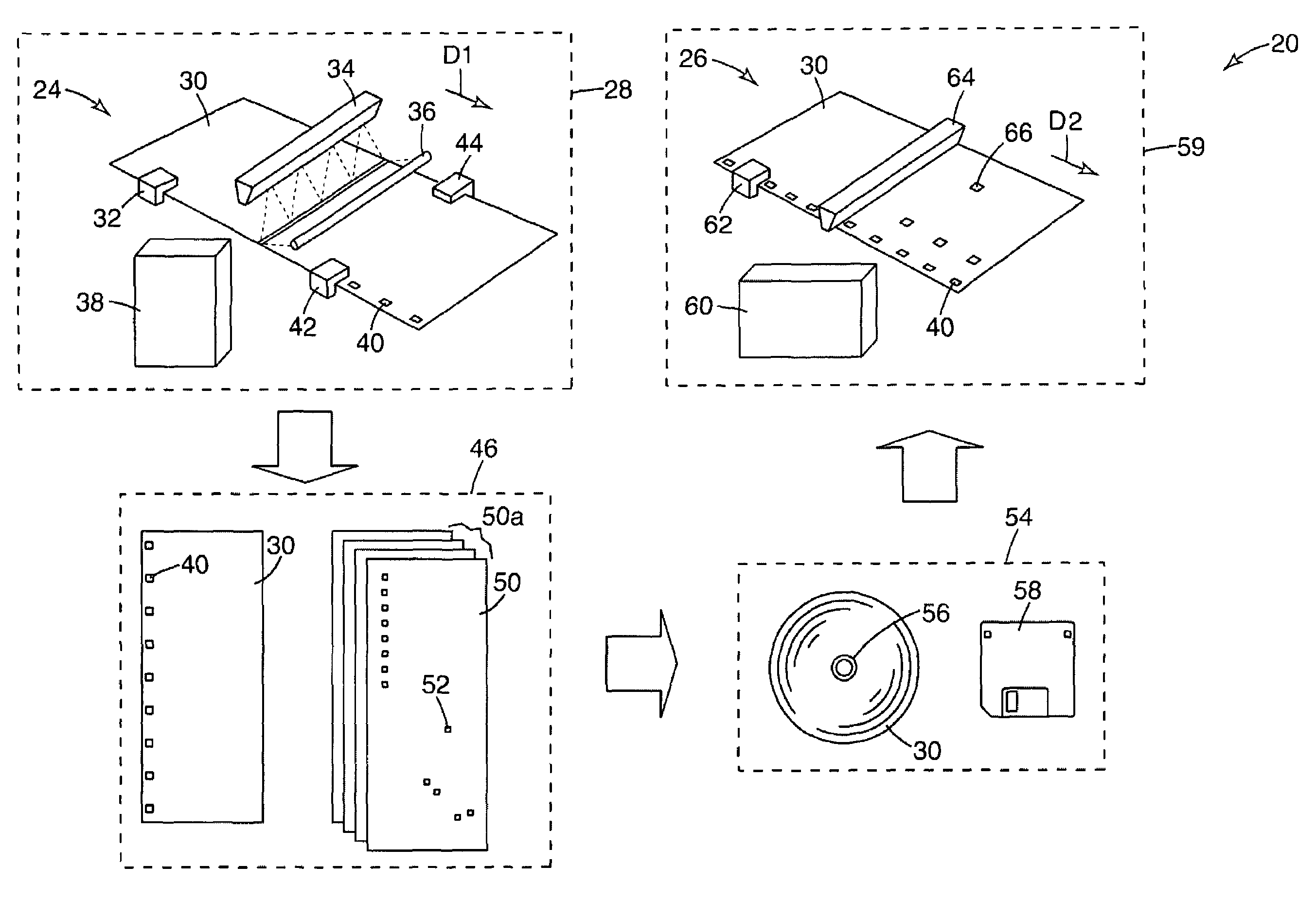
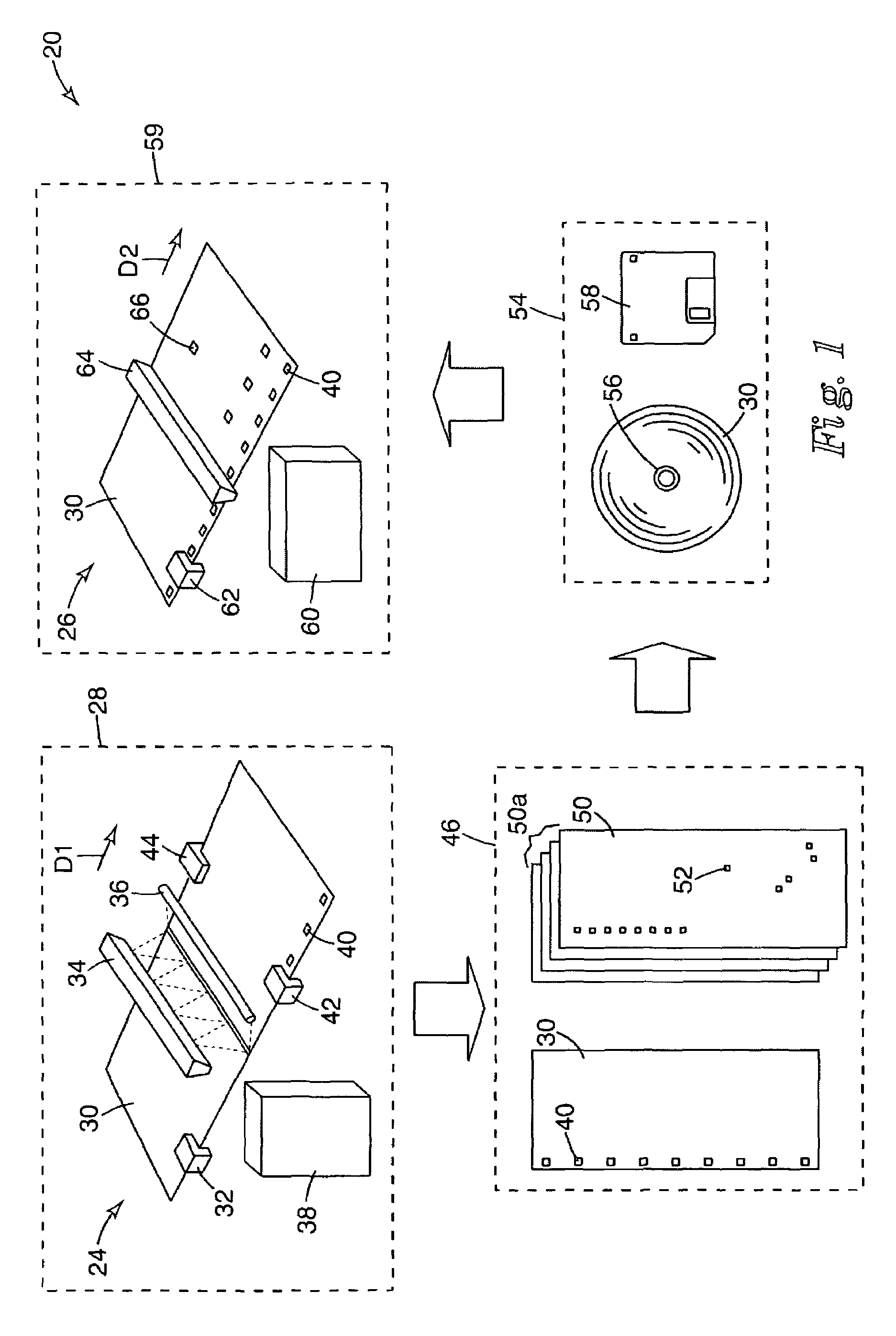
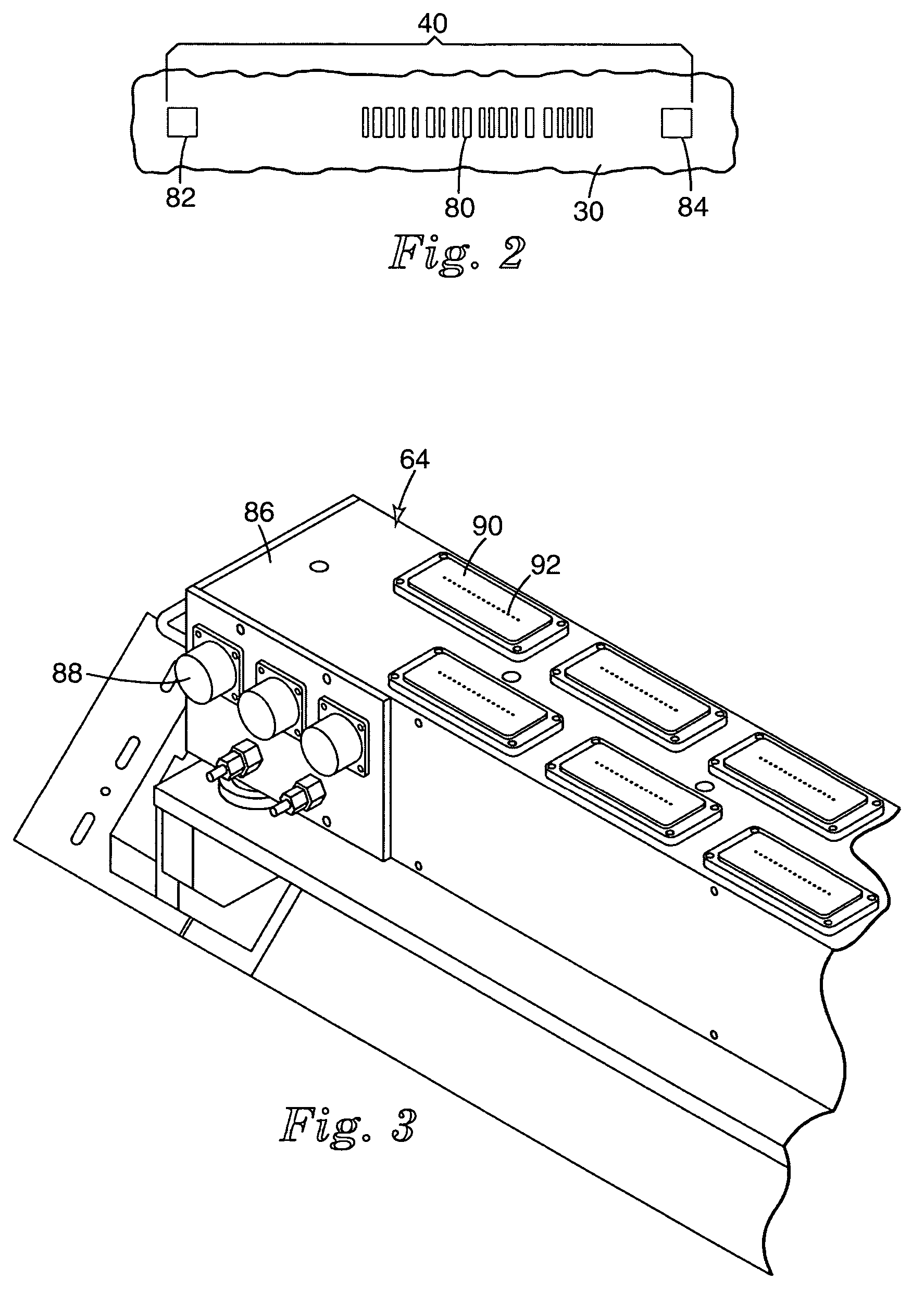
[0054]A model 6800 Lynx printer was adapted to print along the edge of a web so as to serve as a fiducial marker, and was used to print fiducial marks on a moving polymeric web. Each of these fiducial marks included a bar-code and a fiducial position generally as depicted in FIG. 2. The polymeric web was formed from transparent polyester 5 mils thick, commercially available from 3M Company, St. Paul, Minn.

[0055]The web, bearing its fiducial marks, was then directed to an inspection module that imaged sequential portions of the web. This imaging was accomplished by a model AT71XM2CL4010-BA0 camera, commercially available from Atmel of San Jose, Calif. The web was viewed backlit by a lighting module commercially available from Schott-Fostec, LLC, of Alexandria, Va. Digital information from the camera was sent to a model Precision 530 digital computer, commercially available from Dell Computer Corp. of Round Rock, Tex. There it was processed with an initial algorithm to identify region...

example 2

[0056]The web of example 1 was placed in motion, unwinding from its spool in the reverse direction from which it was wound. It was directed past a fiducial reader including a model Legend 530 camera, commercially available from DVT of Duluth, Ga. Positional control over the web as it passed by the fiducial reader was provided by a servo position controller commercially available from Accuweb of Madison Wis., based on information from the web edge sensor commercially available as model 1.5X3U 4043-01, also from Accuweb. The illumination of the web at the fiducial reader was provided by a backlight module commercially available from Advanced Illumination of Rochester, Vt. The output of the camera was directed to a web marker controller comprising a model Precision 530 digital computer, commercially available from Dell Computer Corp., so that information localizing the fiducial marks on the web could be obtained.

[0057]The processor in the web marker controller was also provided with th...

example 3

[0059]The web according to Example 1 was moved and marked generally according to description in Example 2, except that the web marker controller was provided with a subsequent algorithm designed to use distinguish actual defects rendering that portion of the web unsuitable for a particular contemplated end-use from other anomalies among the extracted information in the electronic map. During the run, the web marker controller was further programmed to send commands to the web marker to place locating marks on only those anomalies that qualified according to the subsequent algorithm as actual defects.


PUM

PropertyMeasurementUnit
thickaaaaaaaaaa
lengthaaaaaaaaaa
lengthaaaaaaaaaa

Abstract

A system for the characterization of webs that permits the identification of anomalous regions on the web to be performed at a first time and place, and permits the localization and marking of actual defects to be performed at a second time and place.

Description

TECHNICAL FIELD[0001]The present invention relates to automated inspection systems, and more particularly to a system and device for marking moving webs so as to identify the specific location of defects.BACKGROUND[0002]Inspection systems for the analysis of moving web materials have proven critical to modern manufacturing operations. Industries as varied as metal fabrication, paper, non-wovens, and films rely on these inspection systems for both product certification and online process monitoring. They provide value in two major areas. First, they can be used to measure and report product quality in real-time, thereby enabling continuous optimization of the manufacturing process. Second, they are used to identify defective material, enabling that material to be segregated before shipment to the customer. Unfortunately, accurate identification of defective areas can be extremely difficult depending on the nature of the web combined with the time and place of product converting.[0003...

Claims


Application Information

Patent Timeline
Patent Type & Authority Patents(United States)
IPC IPC(8): G06K9/00D06H1/02D06H3/00D06H3/08G01N21/84G01N21/89G01N21/892G01N21/898
CPCD06H1/02D06H3/00D06H3/08G01N21/89G01N21/8422G01N2021/8927G01N21/8983G01N2021/8917G01N2021/8918G01N21/88
Inventor FLOEDER, STEVEN P.MASTERMAN, JAMES A.SKEPS, CARL J.
Owner 3M INNOVATIVE PROPERTIES CO
Why Eureka
Try Eureka