Deburring by hobbing with integrated secondary deburring without a smoothing tool

a technology of secondary deburring and hobbing, which is applied in the direction of belt/chain/gearring, domestic applications, and teeth of gears, etc., can solve the problems of prolonging the machining time of the milling machine, consuming a lot of time and labor, and reducing the efficiency of the machine tool, so as to achieve the effect of simple machine tool structure, low cost and easy maintenan

Active Publication Date: 2009-12-01
FELSOMAT
View PDF16 Cites 12 Cited by
  • Summary
  • Abstract
  • Description
  • Claims
  • Application Information

AI Technical Summary

Benefits of technology

[0008]By contrast, the object of the present invention is to provide a method whereby well-deburred toothed workpieces may be produced quickly and at low cost.SUMMARY OF THE INVENTION
[0025]A most especially preferred variant of the method provides that, in steps a) and b), during or after pre-milling of an unmachined part at the machining position, cutting is also performed. The additional cutting operation removes the axial projection of material, produced by the pre-milling, before the chamfering operation takes place. The chamfering operation then takes place at a better defined edge, and the material redistributed during chamfering is reduced. The latter reduces the size of the deformation bead after the chamfering operation.

Problems solved by technology

That procedure is very time-consuming and laborious, however.
A disadvantage with that method is the amount of time taken for all the steps of the method.
The chamfer milling does, however, prolong the machining time on the milling machine.
Furthermore, the special milling cutter is expensive and is difficult to re-grind.

Method used


Image

  • Deburring by hobbing with integrated secondary deburring without a smoothing tool
  • Deburring by hobbing with integrated secondary deburring without a smoothing tool
  • Deburring by hobbing with integrated secondary deburring without a smoothing tool

Examples


Embodiment Construction

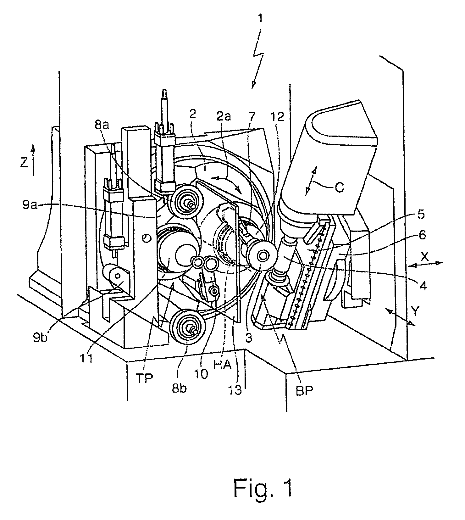
[0037]FIG. 1 shows a machine tool 1 with which the operating method according to the invention may be used.

[0038]The machine tool 1 has a rotary holder 2 which is in the form of a drum and which is rotatable by a motor about a horizontally extending main axis HA in the direction of the arrow 2a. Disposed on the rotary holder 2 are a first workpiece spindle 11 and a second workpiece spindle 12. A respective workpiece may be clamped to each of the workpiece spindles 11, 12, for example by means of a chuck, and may be set in rotation by a motor. The axes of rotation of the workpiece spindles 11, 12 extend parallel to the main axis HA and are at the same distance from it. In the state shown, a workpiece 3 is fastened only to the second workpiece spindle 12. A transparent shield 13 is arranged between the workpiece spindles 11, 12 in order to prevent chips from flying between the workpiece spindles 11, 12.

[0039]The rotary holder 2 is situated in FIG. 1 in a first rotated position. In tha...


PUM

PropertyMeasurementUnit
timeaaaaaaaaaa
timeaaaaaaaaaa
distanceaaaaaaaaaa

Abstract

The invention relates to a method for tooth-machining of workpieces (3), especially gear wheels, comprising milling, deburring by hobbing and integrated secondary deburring. The method proceeds on a machine tool (1) having two workpiece spindles (11, 12) which may exchange places. A workpiece (3) is mounted on a first workpiece spindle (11), followed by the workpiece spindles (11, 12) exchanging places, followed by pre-milling and, where applicable, cutting (=deburring by shaving) of the workpiece (3), followed by a further exchange of places, followed by chamfering and cutting of the workpiece (3), followed by a further exchange of places, followed by a finish-milling of the workpiece (3), followed by a further exchange of places, followed by a workpiece change. At the same time, the same procedure takes place on the second workpiece spindle (12), staggered in time by an exchange of places of the workpiece spindles (11, 12). With the method according to the invention, well-deburred toothed workpieces (3) may be produced quickly and at low cost.

Description

[0001]The invention relates to a method for operating a machine tool for tooth-machining of workpieces,[0002]wherein the machine tool has a rotary holder which is rotatable about a main axis HA and which has two workpiece spindles whose spindle axes extend parallel to the main axis HA, especially wherein the spindle axes are each at the same distance from the main axis HA,wherein the rotary holder is rotatable into a first rotated position in which the first workpiece spindle is in a transfer position and the second workpiece spindle is in a machining position,and wherein the rotary holder is rotatable into a second rotated position in which the first workpiece spindle is in the machining position and the second workpiece spindle is in the transfer position.[0003]An operating method of that kind and an associated machine tool are known by way of the “RZ 150” of the company Reishauer AG.[0004]Toothed workpieces, especially gear wheels, are needed in engineering for numerous applicati...

Claims


Application Information

Patent Timeline
Patent Type & Authority Patents(United States)
IPC IPC(8): B23F17/00B23F23/08
CPCB23F17/006B23F23/04B23F19/10Y10T409/101272Y10T409/101749Y10T29/5136Y10T409/106201Y10T409/30616Y10T409/10795Y10T409/101113Y10T29/49476Y10T29/5128Y10T409/107632Y10T409/100795Y10T29/5127Y10T483/16
Inventor JAEGER, HELMUT F.PESCHINA, JUERGEN
Owner FELSOMAT
Why Eureka
Try Eureka