Floating oceanic surfing reef

a technology reefs, which is applied in the field of floating oceanic reefs, can solve the problems of affecting the quality of surfing experience, and affecting the surfing experience of the place offering such waves,

Inactive Publication Date: 2009-12-01
SAUERBIER CHARLES E
View PDF22 Cites 9 Cited by
  • Summary
  • Abstract
  • Description
  • Claims
  • Application Information

AI Technical Summary

Benefits of technology

[0012]Another advantage of this invention is to provide a device for transforming ocean wave energy into preferred surfing waves that can be readily transported to various locations.
[0013]Another advantage of this invention is to provide a device for transforming ocean wave energy into preferred surfing waves that is relatively compact.
[0014]And still another advantage of this invention is to provide a device for transforming ocean wave energy into preferred surfing waves that can be self-supported in water.
[0015]And yet a further advantage of this invention is to provide a device for transforming ocean wave energy into preferred surfing waves that can be placed in proximity of an existing beach to protect against erosion of the beach by wave action.
[0016]And yet another advantage of this invention is to provide a device for transforming ocean wave energy into preferred surfing waves that, because of its mobility, does not present the problem of having to forecast the complex long-term consequences of a fixed man-made ocean reef, but rather presents the opportunity to adjust and keep focused the effects of the device's placement relative to the constantly changing patterns of multiple ocean waves.
[0019]The present invention involves an apparatus, namely a reef, used to transform ocean wave energy into preferred surfing waves. The reef is comprised of a hull having a substantially flat top surface with a vertically convex shape that preferably creates about a seventy degree tangential bow angle with the ocean surface. The bottom portion is tri-hull shaped and includes two side hulls and a center hull. The preferred embodiment is connected to a master vessel by control arms. The control arms can control the depth of the reef in water, thus controlling the wave characteristics. The control arms can also provide a ducting means for ballast pumps on the master vessel. In an alternative embodiment, the reef can be self-supporting in water. The reef can be placed near a beach or natural reef to prevent erosion by wave action. Several reefs can be connected for longer-lasting waves.

Problems solved by technology

Because there are few places where succeeding waves can be counted upon to be uniform for extended periods, the places that do offer such waves are often overcrowded.
When crowded conditions exist, instead of focusing entirely on riding a wave, surfers must also try to avoid encountering and injuring other surfers, which can dampen the quality of the surfing experience.
However, surfers have had mixed reaction to the existing pools, and most have rejected them due to poor surfing wave quality.
Generally, wave pools have been disfavored due to the inadequately designed shape of the pool, which controls wave height in the pool, and the poor bottom, shape, which acts as the reef for the wave to break on.
However, the space available for the wave conditioning prior to the breaking of the waves is not available in wave pools.
Therefore, although advances have been made in wave pool design, the characteristics of waves produced in wave pools have yet to match the ideal quality waves desired by surfers around the world.
However, the production of a man-made reef can require substantial amounts of time and labor, resulting in significant costs.
Similarly, the creation of a man-made reef also requires careful government monitoring and approval, which can also contribute to a delay in completion.
In a like manner, obtaining the land rights to create such a reef can involve much effort as well as cost, and could face delay from court challenges by conservation and environmental groups.
Lastly, even if such a man-made reef were feasible, the time, effort, and costs associated would likely limit the creation of such reefs to locations that contain the resources to build the reef.
While a possibility, this solution does not present an adequate means for allowing surfing and other recreational activities in various locations worldwide.
Another problem closely associated with waves and wave action is the problem of beach erosion.
However, these efforts have been time consuming, costly, and not produced adequate results.

Method used


Image

  • Floating oceanic surfing reef
  • Floating oceanic surfing reef
  • Floating oceanic surfing reef

Examples


Embodiment Construction

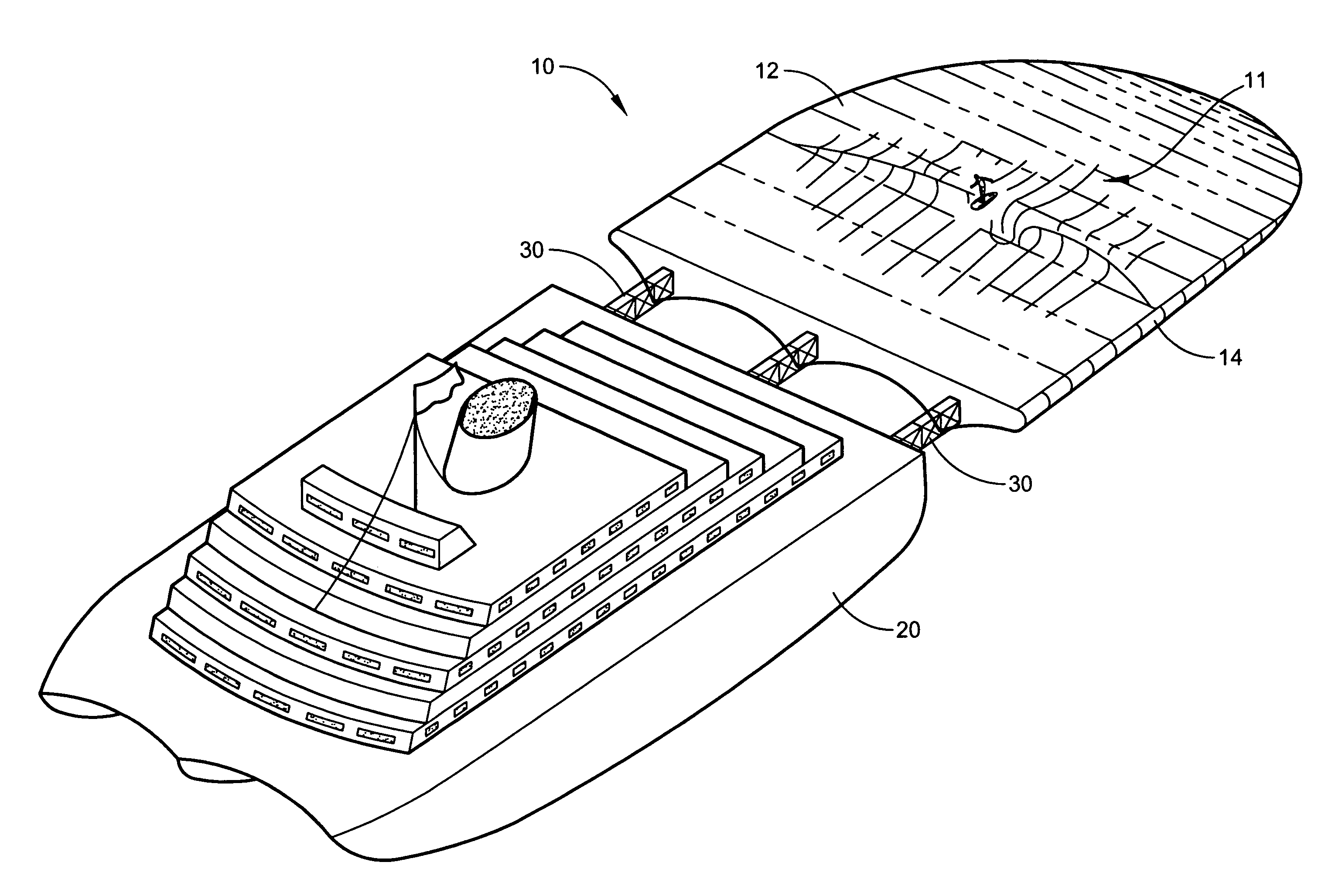
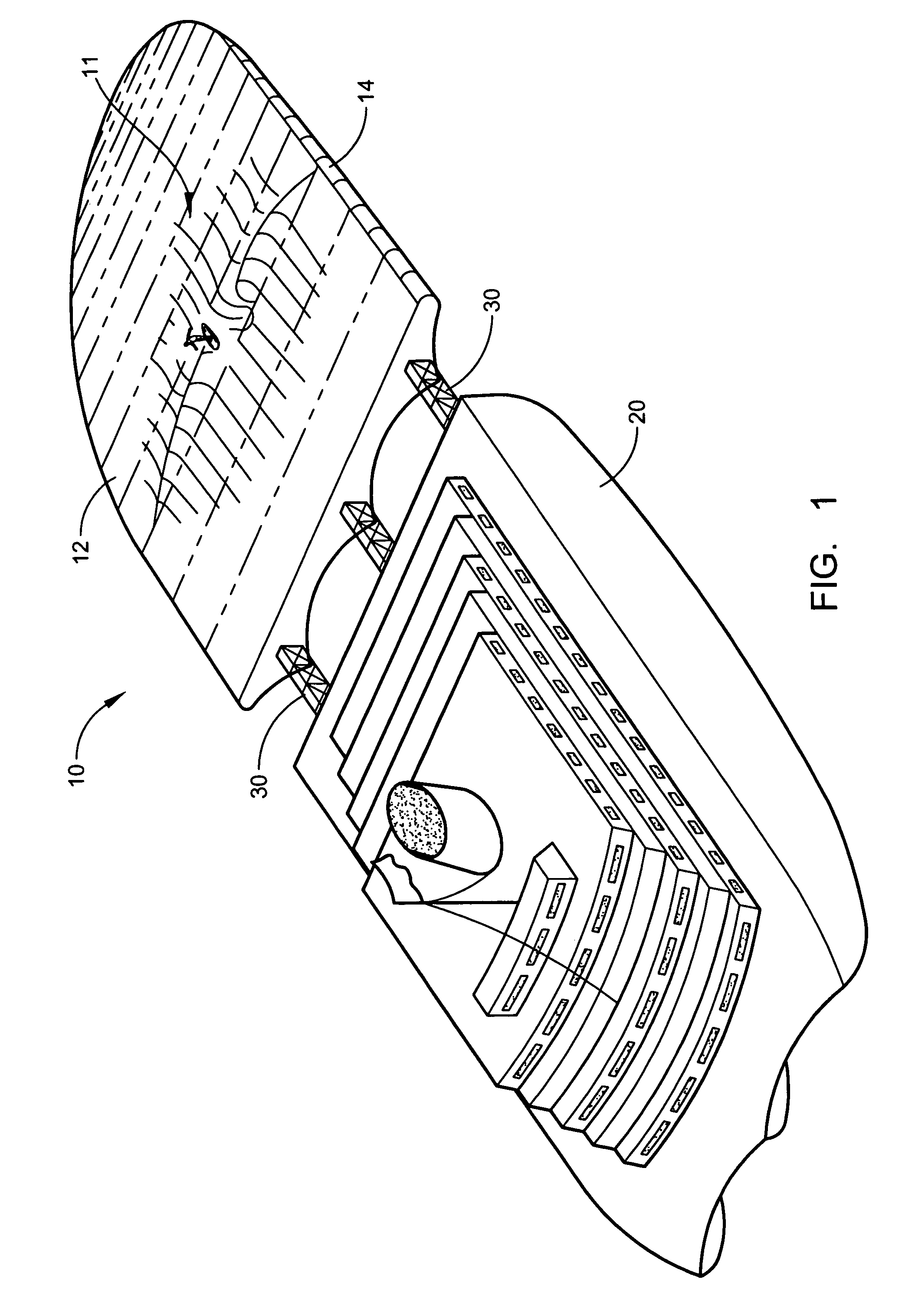
[0034]Referring now to the drawings, wherein similar parts are identified by like reference numerals, there is seen in FIG. 1 a perspective view of the floating oceanic surfing reef 10 attached to a master vessel 20 by control arms 30. The optimum dimensions of floating oceanic surfing reef 10 to produce waves with desirable characteristics are 480 feet in length and 360 feet in width. At these dimensions, floating oceanic surfing reef 10 can transform free ocean wave energy into waves 11 with 20 foot faces and 15 second periods. It is to be understood that the dimensions of floating oceanic surfing reef 10 can be varied to produce waves with certain specific characteristics, such as favoring either a right or left shoulder, as would be recognized by one with ordinary skill in the art. These dimensions can range upward from 125 feet in length and 100 feet in width, as long as the length is approximately 25% larger than the size of the width. Floating oceanic surfing reef 10 is prefe...


PUM


Abstract

The present invention involves an apparatus, namely a reef, used to transform ocean wave energy into preferred surfing waves. The reef is comprised of a hull having a substantially flat top surface with a vertically convex shape that preferably creates about a seventy degree tangential bow angle with the ocean surface. The bottom portion is tri-hull shaped and includes two side hulls and a center hull. The preferred embodiment is connected to a master vessel by control arms. The control arms can control the depth of the reef in water, thus controlling the wave characteristics. The control arms can also provide a ducting means for ballast pumps on the master vessel. In an alternative embodiment, the reef can be self-supporting in water. A single reef or a multiple reef configuration can be placed near shore to help prevent beach erosion by wave action, and or cause beach sand to accumulate. Several reefs can be connected for longer-lasting waves.

Description

BACKGROUND OF THE INVENTION[0001]1. Field of the Invention[0002]The present invention generally relates to the field of surfing reefs. More specifically, the preferred embodiment of the present invention involves a floating reef system adapted to float on or near the surface of an ocean to capture the energy of deep water swells and surface waves and transform the energy into preferred surfing waves.[0003]2. Description of the Related Art[0004]The sport of surfing has attracted enthusiasts all over the world. Many of them travel long distances to locations where ideal surfing conditions exist. Particularly prized by expert surfers are the waves called “the chute” or “the pipeline”, that is, waves which move with sufficient velocity and height that, when they encounter an upwardly sloping bottom of certain configuration, curl forward over the advancing base of the wave to form a tunnel, inside or at the mouth of which expert surfers move laterally across the face of the wave, seeking...

Claims


Application Information

Patent Timeline
Patent Type & Authority Patents(United States)
IPC IPC(8): A63B69/00
CPCB63B1/10E02B3/062B63B35/73A63B69/0093B63B2001/145B63B35/58B63B34/70Y02A10/11
Inventor SAUERBIER, CHARLES E.
Owner SAUERBIER CHARLES E
Why Eureka
Try Eureka