Marine propulsion machine provided with drive shaft

a technology of drive shafts and propulsion machines, which is applied in marine propulsion, machines/engines, and vessel construction, etc., can solve the problems of increased power loss caused by drive shafts driving large-capacity water pumps, difficult to secure a space sufficient, and increase the cost of production, so as to reduce the cost of production and low cost

Inactive Publication Date: 2009-12-01
HONDA MOTOR CO LTD
View PDF7 Cites 14 Cited by
  • Summary
  • Abstract
  • Description
  • Claims
  • Application Information

AI Technical Summary

Benefits of technology

[0009]The present invention has been made under such circumstances and it is therefore an object of the present invention to provide a marine propulsion machine including a drive shaft means including a first drive shaft interlocked with an engine, and a second drive shaft capable of transmitting the power of the first drive shaft to an output gear mechanism, wherein the second drive shaft is disposed on a rear side of the first drive shaft to facilitate securing a space for a water intake and to avoid sucking air together with water through the water intake, and the first drive shaft for driving a water pump is formed in a short length to manufacture the marine propulsion machine at a low cost.
[0015]The upper end of the water intake can be formed at a low vertical position because the water intake is formed in a space extending on the front side of the output gear mechanism with the lower ends thereof at a vertical position coinciding with that of the input gear. Therefore, the water intake is not liable to rise above the surface of the water, suction of air through the water intakes can be avoided and the engine can be properly cooled.
[0017]Thus the second drive shaft is interlocked with the output gear mechanism at a vertical position below the first drive shaft. Therefore, the length of the first drive shaft is shorter than a length in which the first drive shaft is formed when the first drive shaft is directly interlocked with the output gear mechanism. Since the first drive shaft combined with the water pump and required to be formed of an expensive corrosion-resistant material is short, and the cost thereof can be reduced accordingly. The second drive shaft may be formed of an inexpensive ordinary ferrous material. Thus the marine propulsion machine can be manufactured at low cost.

Problems solved by technology

In some cases it is difficult to secure a space sufficient for forming the water intakes when members are disposed and passages are formed on the front side of the drive shafts.
In a marine propulsion machine having a gear case having a gearing holding portion holding an output gear mechanism and provided with water intakes, a suction passage extending between the water intakes and a water pump is long and causes a large pressure loss.
Thus power loss caused by a drive shaft driving the large-capacity water pump increases.
Such a highly corrosion-resistant material is expensive.
Therefore, increase in the length of the drive shaft made of a highly corrosion-resistant material increases the cost of the marine propulsion machine.

Method used


Image

  • Marine propulsion machine provided with drive shaft
  • Marine propulsion machine provided with drive shaft
  • Marine propulsion machine provided with drive shaft

Examples


Embodiment Construction

[0027]Preferred embodiments of the present invention will be described with reference to FIGS. 1 to 7.

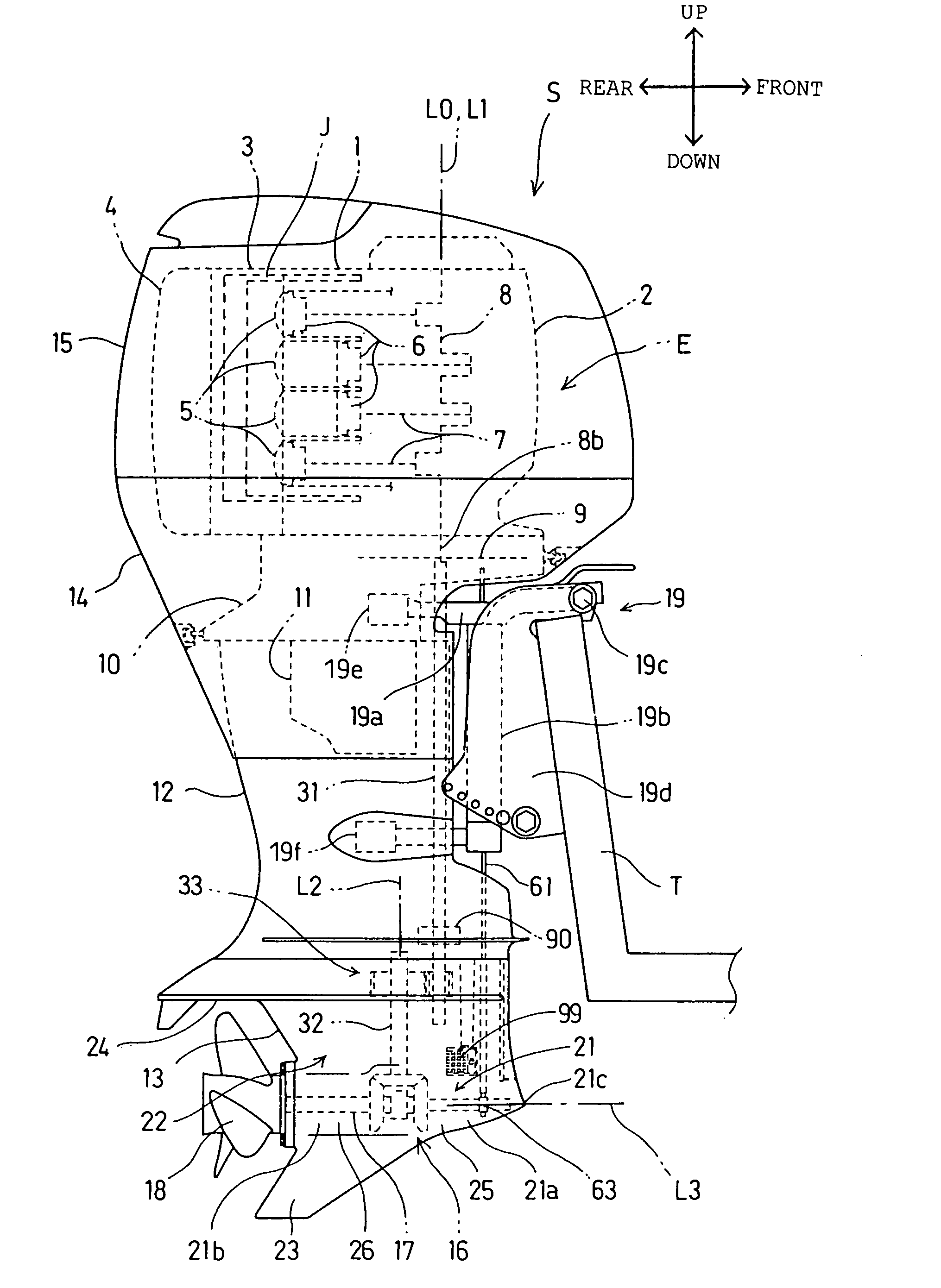
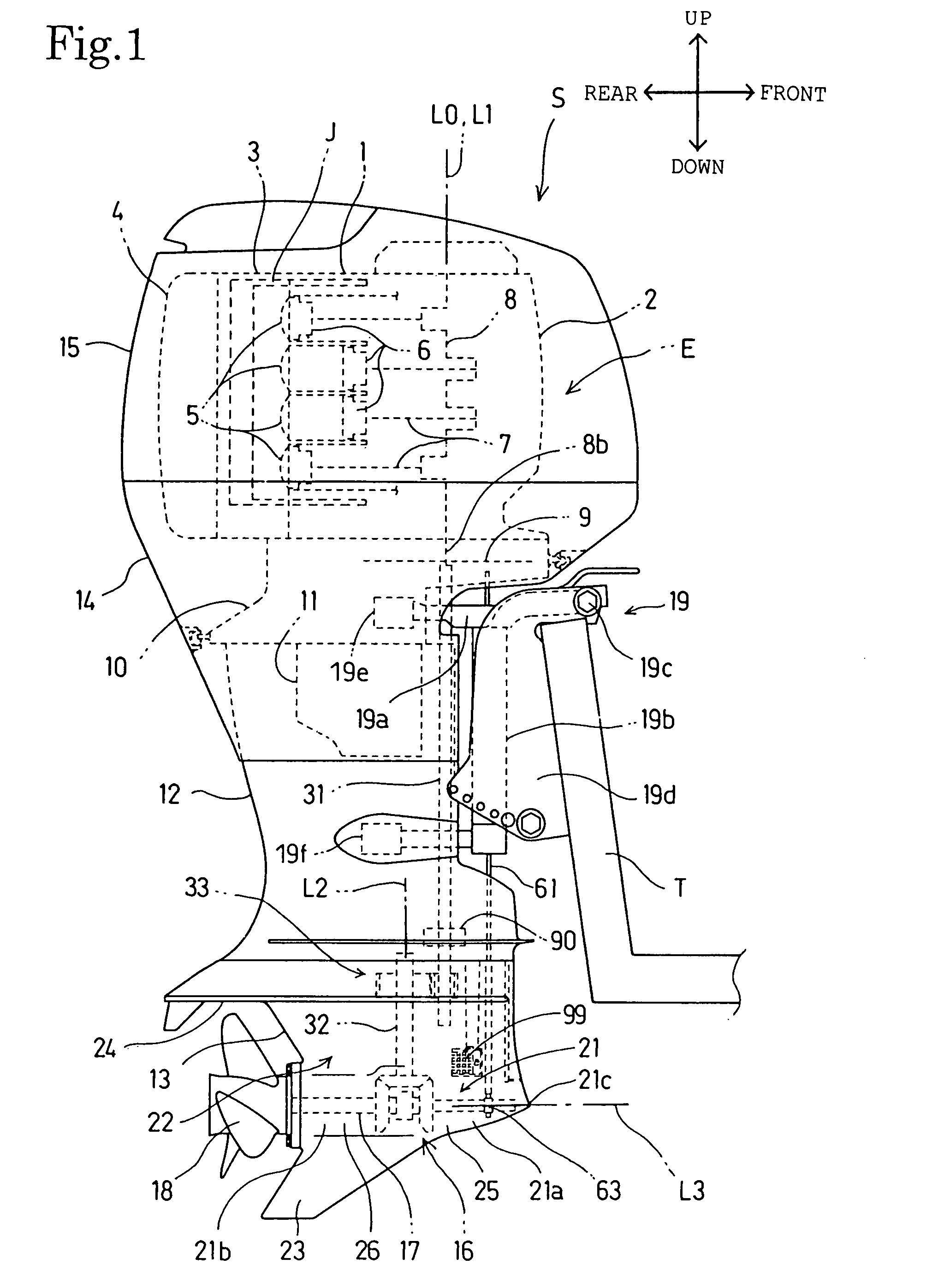
[0028]Referring to FIG. 1, an outboard motor S, namely, a marine propulsion machine, embodying the present invention has a propulsion device and a mounting device 19 for mounting the propulsion device on a hull T. The propulsion device includes an internal combustion engine E, a propulsion unit provided with a propeller 18 driven by the internal combustion engine E to generate thrust, an oil pan 11, cases 12 and 13, and covers 14 and 15.

[0029]The internal combustion engine E is a vertical, water-cooled, multicylinder 4-stroke internal combustion engine. The internal combustion engine E is provided with a crankshaft 8 disposed with its center axis L0 vertically extended, and an overhead-camshaft valve train. The internal combustion engine E has an engine body including a cylinder block 1 integrally provided with four cylinders arranged in a row, pistons 6 fitted in the cylinders for ...


PUM


Abstract

An outboard motor S has a first drive shaft 31 directly interlocked with an engine E, a second drive shaft 32, an intermediate gear mechanism 33 interlocking the first drive shaft 31 and the second drive shaft 32, an output gear mechanism 50 driven by power transmitted thereto through the second drive shaft 32, a propeller shaft 17 driven for rotation by power transmitted thereto through the output gear mechanism 50, and a gear case 13 holding the output gear mechanism 50. The second drive shaft 32 extends downward beyond a vertical position corresponding to the lower end of the first drive shaft 31. The gear case 13 is provided with water intakes 98 through which a water pump 90 sucks water in a space between the first drive shaft 31 and the output gear mechanism 50 with respect to a vertical direction on the front side of the second drive shaft 32. The space for the water intakes 98 can be easily secured because the second drive shaft 32 is disposed on the rear side of the first drive shaft 31.

Description

BACKGROUND OF THE INVENTION[0001]1. Field of the Invention[0002]The present invention relates to a marine propulsion machine including a vertical drive shaft driven for rotation by an engine, an output gear mechanism to which the power of the drive shaft is transmitted, a propeller shaft driven for rotation by power transmitted thereto through the output gear mechanism, and a water pump driven by the drive shaft.[0003]2. Description of the Related Art[0004]Marine propulsion machines are known which are provided with a drive shaft including a first drive shaft interlocked with an engine, and a second drive shaft interlocked with the first drive shaft by an intermediate gear mechanism (see, for example, Japanese Patent Application Publication Nos. 5-52107, 63-97489 and 3-21589. Marine propulsion machines are also known in which a gear case is provided with water intakes formed in parts thereof on the front side of drive shafts and a water pump driven by the drive shaft sucks water thr...

Claims


Application Information

Patent Timeline
Patent Type & Authority Patents(United States)
IPC IPC(8): B63H23/34
CPCB63H20/00B63H20/285B63H20/14
Inventor IDE, SHINICHIKUBOTA, MITSUAKIAKIYAMA, MASAHIRO
Owner HONDA MOTOR CO LTD
Why Eureka
Try Eureka