
Bi-slot tree based tag identification method in RFID systems

a tag identification and bi-slot technology, applied in the field of tag identification methods in rfid systems, can solve the problems of reducing the number increasing the cost of equipment, and so as to reduce the number of inquiries and responses, and the effect of reducing the number of readers

Inactive Publication Date: 2009-12-01
KOREA ADVANCED INST OF SCI & TECH
View PDF9 Cites 7 Cited by
  • Summary
  • Abstract
  • Description
  • Claims
  • Application Information

AI Technical Summary

Benefits of technology

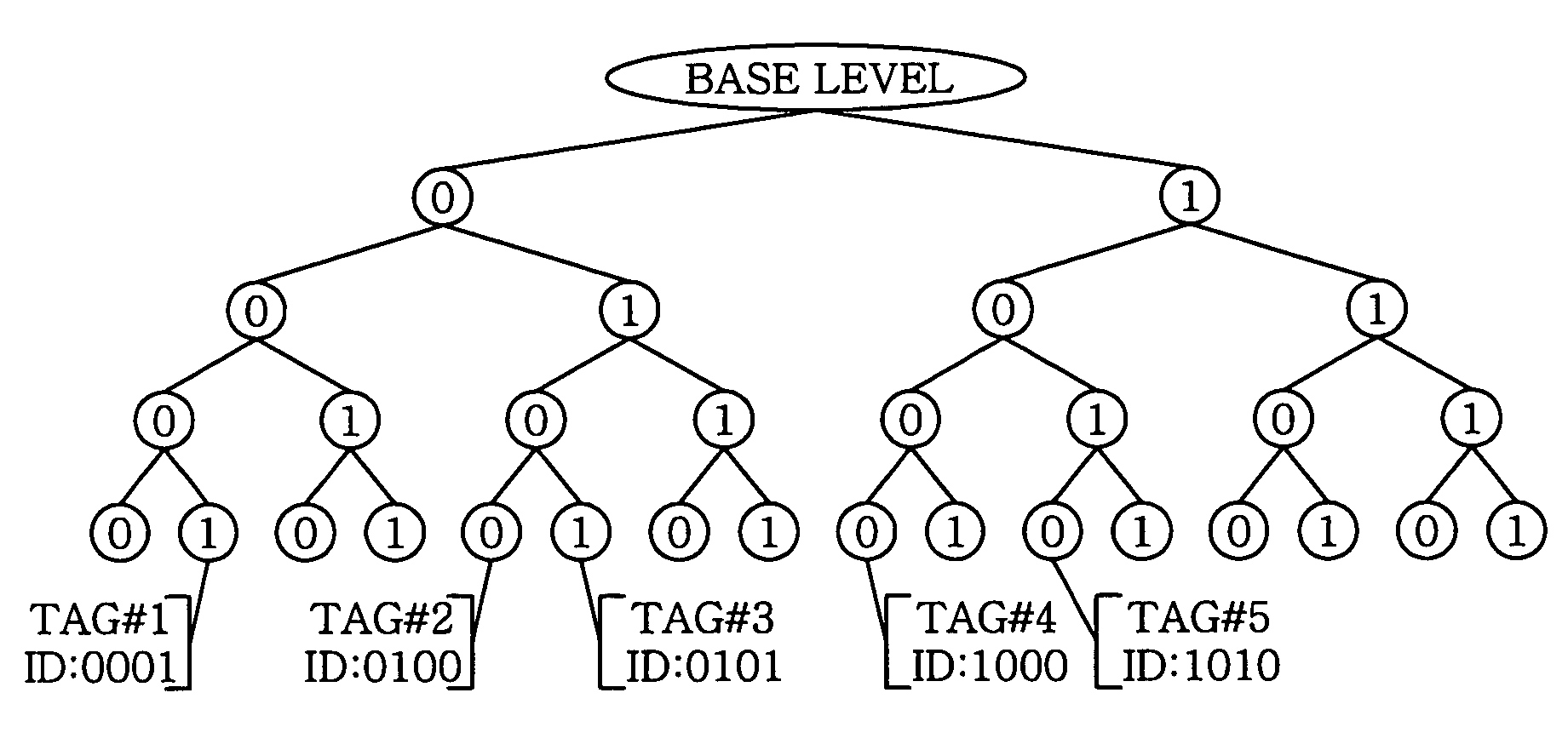
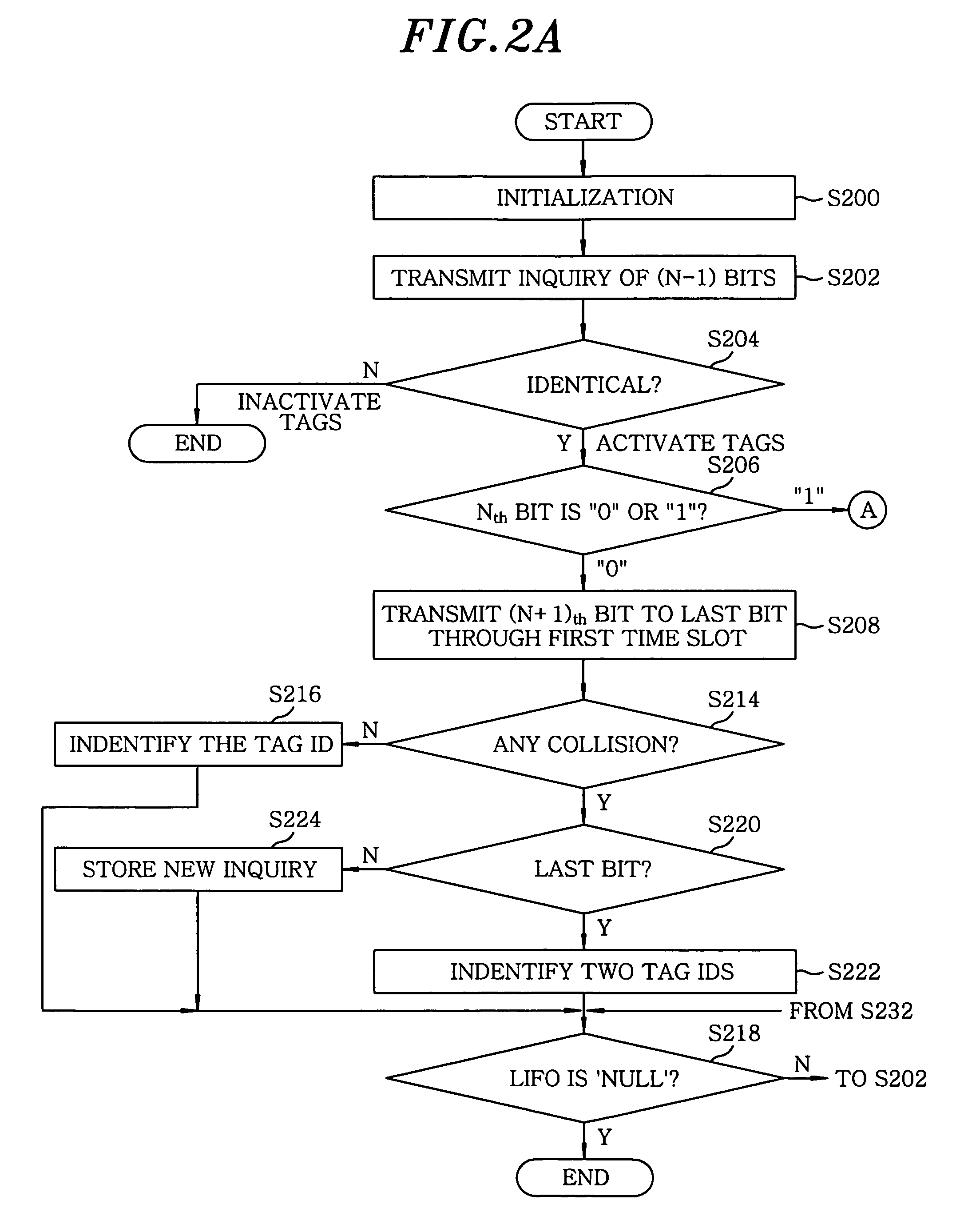
"The present invention provides a bi-slot tree based tag identification method in RFID systems that reduces the number of inquiries and responses between the reader and tags without affecting their responses. This method improves the identification performance of the tag by reducing the reader's inquiries. The method involves transmitting an inquiry of (n−1) bits to each tag, deciding whether the inquiry is identical with the first (n−1) bits of each tag ID, transmitting each tag ID by one bit from (n+1)th bit to a last bit through different time slots based on the nth bit value of each tag ID, checking whether there is a collision among the tag IDs, and identifying each tag ID based on the check result. This method reduces the number of collisions and improves the identification performance of the tag."

Problems solved by technology

However, since the RFID has problems with the reliability of the identified data and the delay of the technology standardization, researches on anti-collision protocols have been required to improve the characteristics of a read rate and an identification speed.
Meanwhile, there are generally two types of collisions: reader collisions and tag collisions.
However, in case of the tag collisions, the tags which are currently used or which will be used in the large scale distribution and circulation fields are low-cost passive tags, resulting in some restrictions such as complexity of calculating, battery absence and cost increase by the memory size when applying usable anti-collision protocols thereto.
In the memory based algorithm, which can be grouped into a splitting tree algorithm and a bit-arbitration algorithm, the reader's inquiries and the responses of the tags are stored and managed in the tag memory, thereby causing an equipment cost increase.
Meanwhile, the probabilistic methods are based on slotted aloha based protocols which do not guarantee a 100% read rate but reduce the probability of tag collisions occurring.
However, the increase of the slots in each frame causes the increase of frame transmitting time.
In spite of this contradiction, it is difficult to calculate the number of the identification objects, i.e., tags, accurately, so the appropriate number of slots required to each frame and the end point are calculated depending on the probabilistic methods.
Thus, the ALOHA based anti-collision algorithm has problems in that it cannot provide the complete tag identification; and high efficiency in the tag identification cannot be expected because the slots where collisions occurred are retransmitted.
Furthermore, if there is a collision in the query tree algorithm, the trees are split as in the binary tree working algorithm and retransmitted after increasing one bit to the inquiry, thereby causing the waste of the time.
Although the performance can be enhanced by taking benefit while processing the responses of the tags according to such methods, the current researches focus on only half of the improvable part, but do not consider the performance which can be enhanced by focusing on the reader's inquiry.

Method used


Image

  • Bi-slot tree based tag identification method in RFID systems
  • Bi-slot tree based tag identification method in RFID systems
  • Bi-slot tree based tag identification method in RFID systems

Examples


Embodiment Construction

[0038]Hereinafter, preferred embodiments of the present invention will be described in detail with reference to the accompanying drawings so that they can be readily implemented by those skilled in the art.

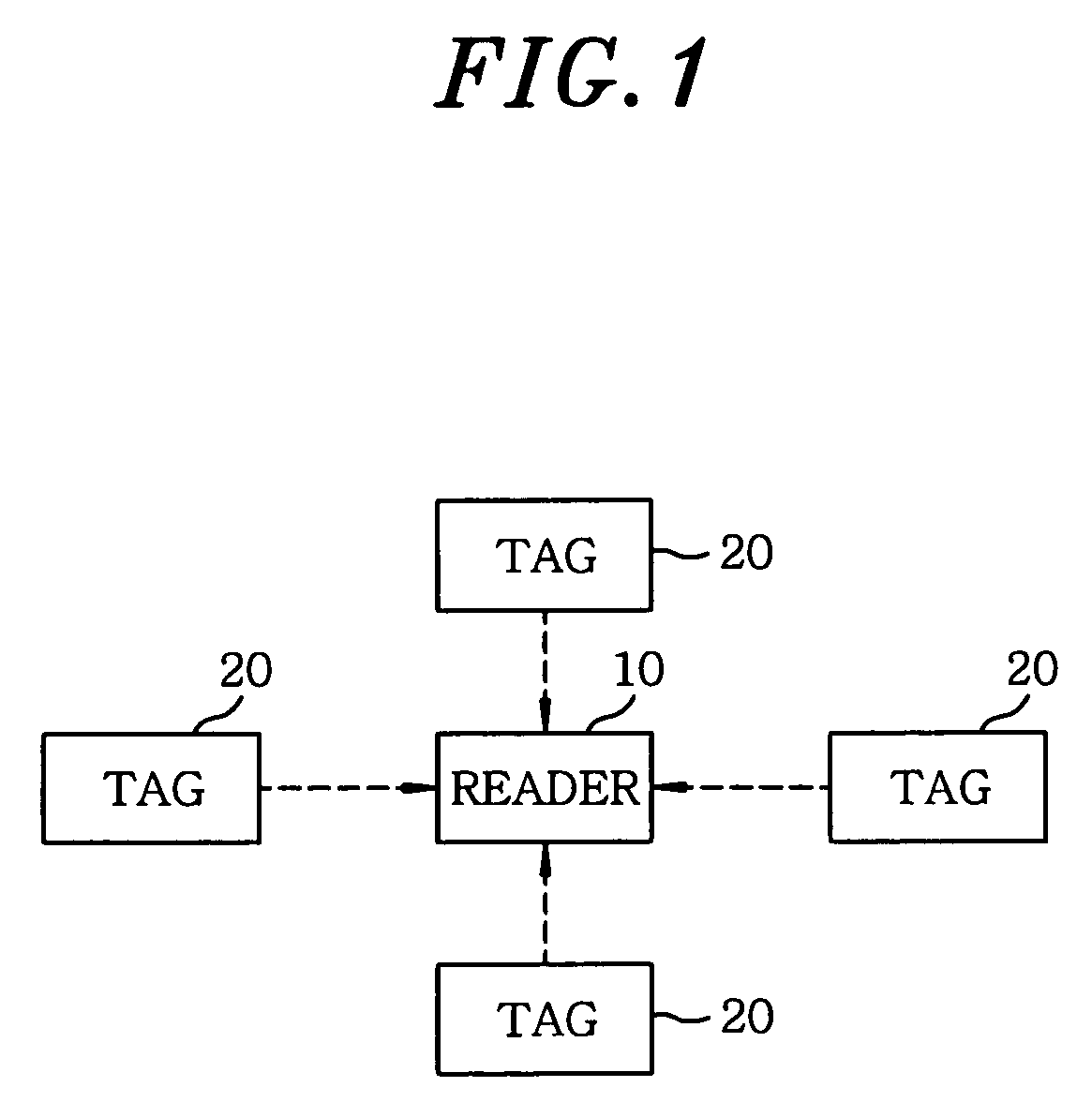
[0039]FIG. 1 is a schematic diagram of a RFID system capable of implementing a scanning based tag identification method in accordance with the present invention.

[0040]As shown in FIG. 1, the RFID system where the tag identification method of the present invention is implemented includes a reader 10 and at least one tag 20. The RFID is a technology capable of reading information of tags through RF waves after attaching the tags to objects. This technology can be applied to various fields such as distribution management, security, circulation and the like. By changing an existing contact barcode into RF, it cannot only read the information faster than the barcode but also has the advantage that the restriction of the operation range is alleviated. Further, it takes an additional adv...


PUM


Abstract

A bi-slot tree based tag identification method in RFID systems includes (a) transmitting an inquiry of (n−1) bits to each tag at the reader; (b) deciding whether the inquiry of (n−1) bits are identical with first (n−1) bits of each tag ID when receiving the inquiry of (n−1) bits at each tag within a readable range of the reader; (c) transmitting each tag ID by one bit from (n+1)th bit to last bit thereof to the reader through different time slots based on nth bit value of each tag ID at the tags whose first (n−1) bits are identical with the inquiry of (n−1) bits; and (d) at the reader, checking whether there is a collision among the tag IDs received from the tags and identifying each tag ID of the tags based on the check result.

Description

FIELD OF THE INVENTION[0001]The present invention relates to a tag identification method in RFID systems; and, more particularly, to a bi-slot tree based tag identification method in the RFID systems capable of reducing the reader's inquiries.BACKGROUND OF THE INVENTION[0002]As well known, RFID (Radio Frequency Identification) is one of automatic identification methods such as a barcode, a magnetic sensor, an IC card and the like; and means a technology used for wirelessly identifying data stored in a tag's microchip by using an ultra-short wave or a long wave.[0003]Such RFID is regarded as a substitute technology for the barcode which is currently used in distribution and circulation fields and financial services. The RFID has advantages in that there is no need of an extra identification process such as contact required in a conventional barcode method in order to achieve tag information or a reader scan in a visibility range and in that huge amounts of data can be sent.[0004]Howe...

Claims


Application Information

Patent Timeline
Patent Type & Authority Patents(United States)
IPC IPC(8): G08B13/14
CPCG06K7/10049G06K7/0008G06K17/00G06K19/07
Inventor CHOI, JI HWANLEE, HYUCKJAELEE, DONGWOOKJEON, HYOUNGSUKJUNG, HOIYOON
Owner KOREA ADVANCED INST OF SCI & TECH
Learn More