Non-scanning radar for detecting and tracking targets

a radar and target technology, applied in direction finders, instruments, measurement devices, etc., can solve the problems of long dwell time on targets, expensive systems based on phased array antennas, and systems no longer suitable for modern warfar

Inactive Publication Date: 2009-12-01
MARK RESOURCES
View PDF26 Cites 54 Cited by
  • Summary
  • Abstract
  • Description
  • Claims
  • Application Information

AI Technical Summary

Problems solved by technology

For fast-moving targets, especially at short range, the surveillance volume must be rapidly scanned, which leads to a short dwell time on a target.
These conflicting requirements have traditionally led to an expensive system based on a phased array antenna, or to multiple systems designed specifically for each function.
However, such systems are no longer appropriate for modern warfare, such as combating insurgents, where an attack can occur at short range, from any direction, and without warning.
There is a practical limit to the transmit power, as increasing power beyond some relatively low level has a disproportionate impact on system cost and reliability.
Until now, there has also been a practical limit to the dwell time for detecting targets in clutter, as in the prior art, the target had to be considered essentially stationary within a range gate and Doppler filter during this time.
However, increasing the antenna gain has two effects: (1) the antenna will be larger, more expensive, and more difficult to transport and setup; and (2) the beam will be narrower, providing less time on target for a given time to scan the surveillance volume.
Because of mechanical inertia, the fast scan rate and long dwell time are incompatible for a radar that employs a conventional reflector antenna.
One solution would be to use separate antennas (or separate radars) for search and track, but mechanical inertia in the antenna again limits the number of widely dispersed targets that can be tracked at any one time.
Phased arrays, however, are typically large, immobile, and very expensive.
Three such arrays would be required to cover all directions, which is a tripling of the size and cost of an already large and expensive system.
Such systems are totally unsuitable for modern warfare, where targets can appear suddenly at short range, and from any direction.

Method used


Image

  • Non-scanning radar for detecting and tracking targets
  • Non-scanning radar for detecting and tracking targets
  • Non-scanning radar for detecting and tracking targets

Examples


Embodiment Construction

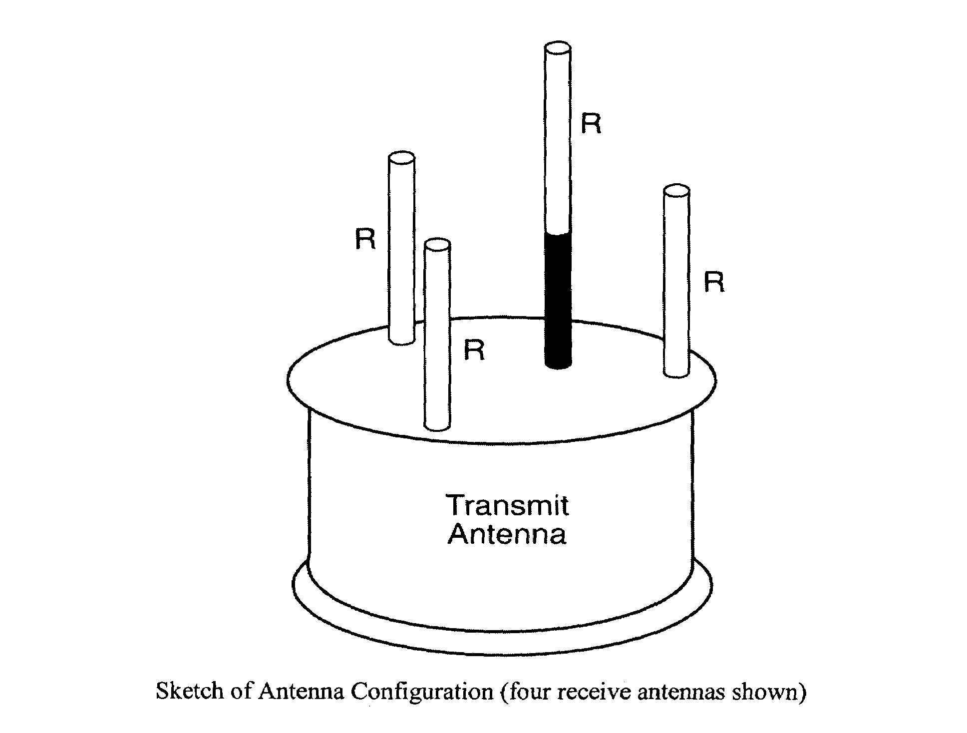
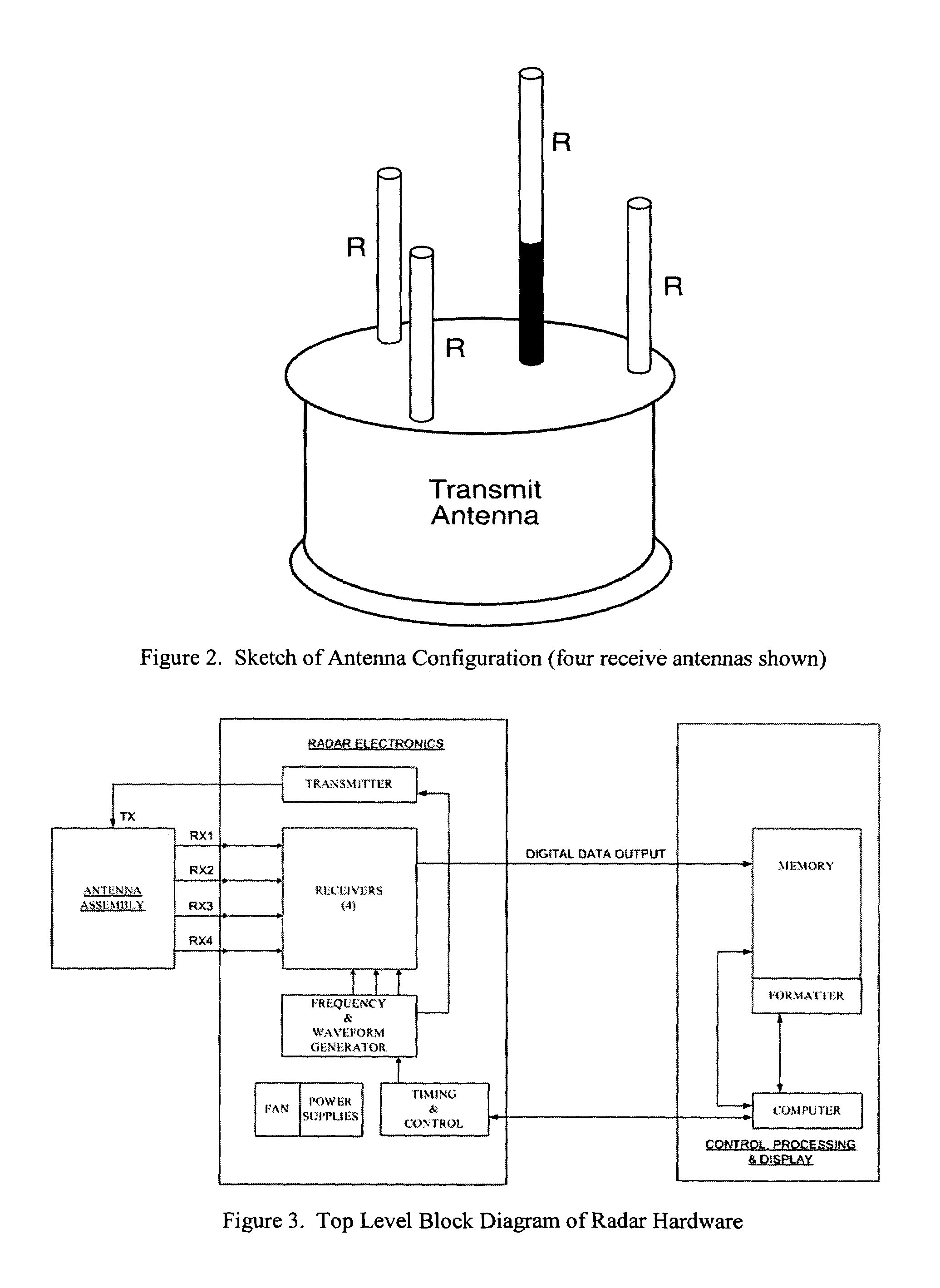
[0018]The preferred embodiments of the present invention are based on replacing the traditional narrow antenna beam with one that illuminates the entire surveillance sector continuously, eliminating the scan entirely. The antenna is thus simple and inexpensive. The need for angle measurements is met with a simple interferometer, utilizing multiple antennas on receive, and the loss in antenna gain is offset by a much longer processing time for detection purposes (hereinafter called long dwell time or long-term processing, namely long in comparison to that used in a conventional surveillance radar). Although this long-term signal processing is much more intensive than that required for the traditional approach, it is nevertheless practical in the present modern computer age. In effect, the system expense is transferred from the antenna to the signal processor. In this regard, it is the software that is initially expensive, not the digital hardware, but the former is a non-recurring ex...


PUM


Abstract

Radar for detecting and tracking short range airborne targets using a non-scanning beam to illuminate the entire search space, and processing the return signals from a plurality of spaced apart receive antennas. Target angle in one plane may be determined by coherent processing of the returns from the plurality of receive antennas. Spacing the receive antennas apart in three dimensions allows determining of two angles, such as azimuth and elevation. Processing of the returns may be coherent or noncoherent, or returns may be processed both coherently and noncoherently. Programmability of the processing algorithms and parameters provide flexibility in applications, as well as flexibility based on such things as the target type and its range. Exemplary applications are disclosed.

Description

CROSS-REFERENCE TO RELATED APPLICATION[0001]This application claims the benefit of U.S. Provisional Patent Application No. 60 / 565,942 filed Apr. 28, 2004.BACKGROUND OF THE INVENTION[0002]1. Field of the Invention[0003]The present invention relates to the field of radar detection and tracking systems.[0004]2. Prior Art[0005]In conducting a radar search for airborne targets, it is conventional practice to use a narrow antenna beam. For fast-moving targets, especially at short range, the surveillance volume must be rapidly scanned, which leads to a short dwell time on a target. On the other hand, for tracking and discriminating targets, a much longer dwell is needed. These conflicting requirements have traditionally led to an expensive system based on a phased array antenna, or to multiple systems designed specifically for each function. Such expense has been justified in conventional warfare where the general location of the enemy is known, the engagement is fairly static, and the equ...

Claims


Application Information

Patent Timeline
Patent Type & Authority Patents(United States)
IPC IPC(8): G01S13/48
CPCG01S3/46G01S13/46G01S13/343G01S7/35
Inventor RIHACZEK, AUGUST W.MITCHELL, RICHARD L.
Owner MARK RESOURCES
Why Eureka
Try Eureka