Fuser unit with cleaning mechanism and image forming apparatus having the same

a cleaning mechanism and image forming technology, applied in the direction of electrographic process apparatus, instruments, optics, etc., can solve the problems of fuser roller surface dirty, fuser hardening in non-conductive state, power saving mode damage to fuser rollers, etc., to prevent the effect of becoming dirty

Inactive Publication Date: 2009-12-08
SHARP KK
View PDF12 Cites 9 Cited by
  • Summary
  • Abstract
  • Description
  • Claims
  • Application Information

AI Technical Summary

Benefits of technology

[0018]The present invention has been achieved in consideration of the circumstances and provides a mechanism capable of preventing backward travel of a web sheet accompanying rotation of a fuser roller so that it can be prevented from becoming dirty. Another object of the invention is to provide a mechanism capable of preventing the travel of a web sheet at the time of removing a paper jam in a fixing unit.
[0021]The fuser unit of the invention has the first reverse rotation preventing mechanism for preventing rotation of the press roller from rotating in the opposite direction to the winding direction of the cleaning member. Consequently, when the fuser roller rotates or a jammed sheet is removed, a web sheet can be prevented from traveling in the opposite direction to the winding direction of the web sheet. Therefore, it becomes unnecessary to wind the web sheet excessively in consideration of the backward travel, so that the web sheet can be used effectively. The cleaning capability can be maintained without burden of extra cost on the user. At the time of removing a jammed sheet, a surface of the fuser roller can be prevented from becoming dirty or damaged due to backward travel of the web sheet. In addition, occurrence of a wrinkle causing poor cleaning and breakage of the web sheet can be prevented. In other words, by preventing the backward travel of the web sheet, deterioration in the printing quality can be prevented.

Problems solved by technology

A problem such that the toner hardened in the non-conductive state or a power saving mode damages the fuser rollers in current-carrying operation after that becomes obvious.
If the web sheet is wound in the forward direction, the toner taken by the web sheet passes through the nip portion and returns to the fuser roller side during the passage, and it is feared that the surface of the roller becomes dirty.
In a low temperature state, there is the possibility that hardened toner damages the surface of the roller.
As a result, the frictional force received from the fuser roller also becomes nonuniform, and it causes a wrinkle in the web sheet.
When a wrinkle occurs in the web sheet, the contact to the surface of the fuser roller becomes nonuniform, and it causes poor cleaning.
However, as the printing process speed increases, in some cases, the tension becomes insufficient.
When the toner enters the nip portion, it causes dirt or damage in the fuser roller and a wrinkle in the web sheet.
A member suitable for such a use is not common but special and expensive.
From this viewpoint, it is unpreferable to wind the web sheet excessively.
When the web sheet moves in the case where the sheet is pulled to the transfer side, the web sheet is fed uselessly.

Method used


Image

  • Fuser unit with cleaning mechanism and image forming apparatus having the same
  • Fuser unit with cleaning mechanism and image forming apparatus having the same
  • Fuser unit with cleaning mechanism and image forming apparatus having the same

Examples


Embodiment Construction

[0033]Regarding the fuser unit of the present invention, it may further include a second reverse rotation preventing mechanism for preventing rotation of the wind roller from rotating in the opposite direction to the winding direction of the cleaning member.

[0034]Further, the feed roller may further include a rotation preventing mechanism, wherein the feed roller may feed the cleaning member intermittently, and the rotation preventing mechanism may include a disengaging mechanism to prevent the feed roller from rotating in the feeding direction when the cleaning member is not wound, and to allow the feed roller to rotate in the feeding direction when the cleaning member is wound.

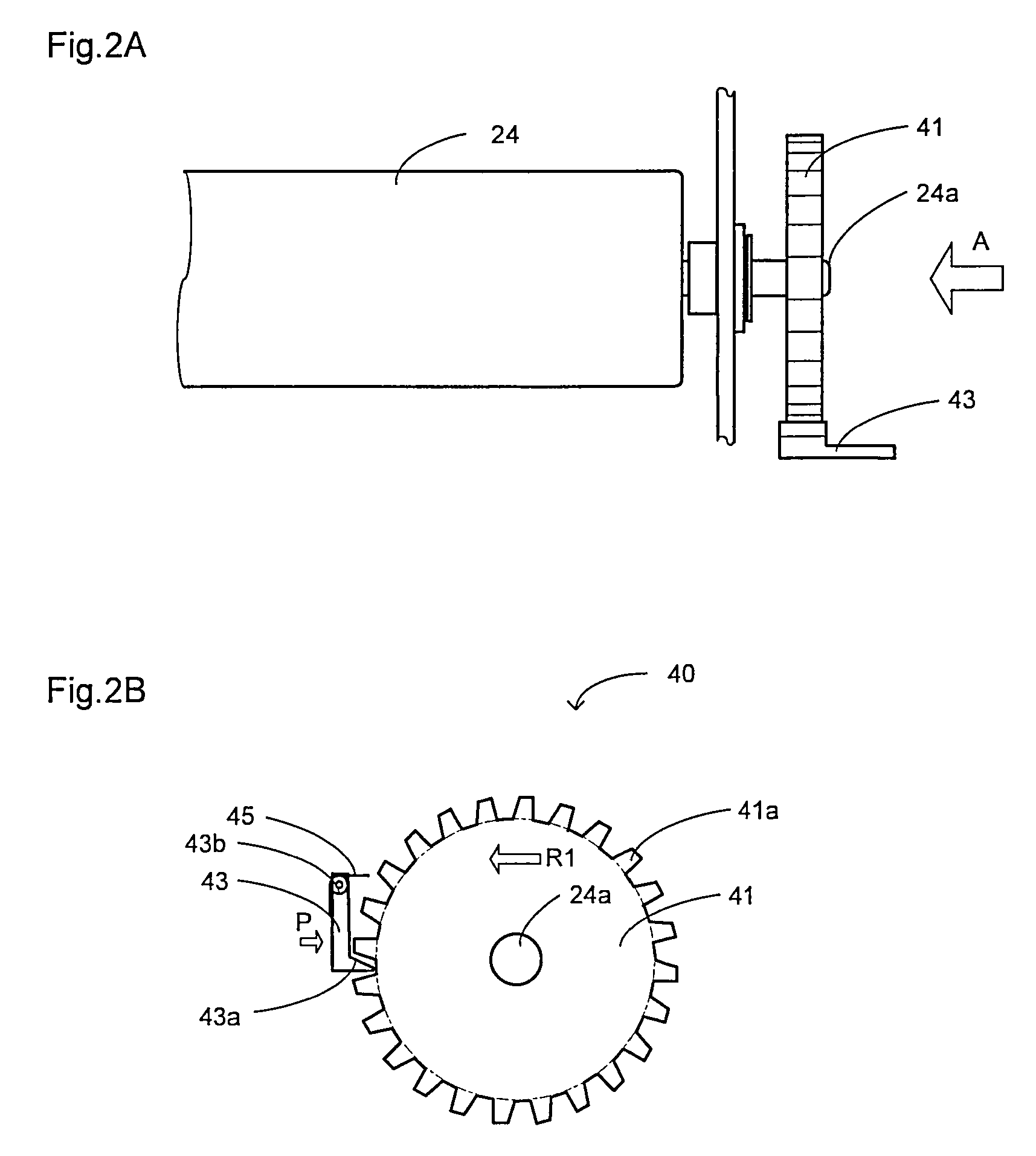
[0035]The first reverse rotation preventing mechanism may be a ratchet mechanism including a ratchet gear which is directly or indirectly coupled to a shaft of the press roller.

[0036]Alternately, the first reverse rotation preventing mechanism may be a one-way clutch which is directly or indirectly coupled t...


PUM


Abstract

A fuser unit with a cleaning mechanism, including: a set of a heat roller and a pressure roller for sandwiching a recording sheet while heating the recording sheet by the heat roller; a feed roller for feeding a band-shaped cleaning member which is windable; a press roller for pressing the fed cleaning member against a surface of the heat roller or the pressure roller; a wind roller for winding the cleaning member which is pressed by the press roller; and a first reverse rotation preventing mechanism for preventing rotation of the press roller from rotating in the opposite direction to the winding direction of the cleaning member.

Description

CROSS-REFERENCE TO RELATED APPLICATION[0001]This application is related to Japanese patent application Nos. 2006-156452 and 2006-244274 which are filed on Sep. 8, 2006 and Dec. 26, 2006 respectively whose priorities are claimed under 35 USC §119, the disclosure of which are incorporated by reference in its entirety.BACKGROUND OF THE INVENTION[0002]1. Field of the Invention[0003]The present invention relates to a fuser unit with a cleaning mechanism and an image forming apparatus having the same.[0004]2. Description of the Related Art[0005]In recent years, the printing process speed of an image forming apparatus is increasing. As the printing process speed increases, improvement in the capability of removing residual toner (cleaning capability) of a cleaning mechanism of a fuser roller in a fuser unit is required. The fuser unit performs fusing with a heat roller and a pressure roller rotating while in contact with each other with pressure. The cleaning mechanism is a mechanism for c...

Claims


Application Information

Patent Timeline
Patent Type & Authority Patents(United States)
IPC IPC(8): G03G15/20
CPCG03G15/2025G03G21/0041
Inventor TATEISHI, YOSHINOBUMINAKUCHI, YASUNORIMIKITA, TOSHIYANANBA, TOYOAKINAGAI, YOSHIYUKINAKATANI, HIROSHI
Owner SHARP KK
Why Eureka
Try Eureka