Thermal flowmeter for measuring a flow rate of fluid

a flow rate and flowmeter technology, applied in the direction of volume/mass flow measurement, measurement devices, instruments, etc., can solve the problems of deteriorating measurement accuracy, deteriorating measurement accuracy, and deteriorating accuracy, so as to reduce errors in measurement accuracy and improve the accuracy of flow rate measuremen

Inactive Publication Date: 2009-12-15
HITACHI LTD +1
View PDF20 Cites 7 Cited by
  • Summary
  • Abstract
  • Description
  • Claims
  • Application Information

AI Technical Summary

Benefits of technology

[0010]An object of the present invention is to reduce errors in measurement accuracy of a fluid flowmeter caused by external thermal influences, and to provide a thermal flowmeter of a fluid with improved accuracy in measurement of a flow rate.

Problems solved by technology

However, when the prior-art flowmeter is used in an internal combustion engine of an automobile or the like, the accuracy in measuring an air flow rate is deteriorated by thermal influences applied externally of the thermal air flowmeter due to heat generated by the internal combustion engine.
Therefore, the flow rate is measured as a smaller value than the actual one, and the measurement accuracy is deteriorated.
That cause of deteriorating the measurement accuracy has not been recognized and no countermeasures have been taken in the prior art.

Method used


Image

  • Thermal flowmeter for measuring a flow rate of fluid
  • Thermal flowmeter for measuring a flow rate of fluid
  • Thermal flowmeter for measuring a flow rate of fluid

Examples


first embodiment

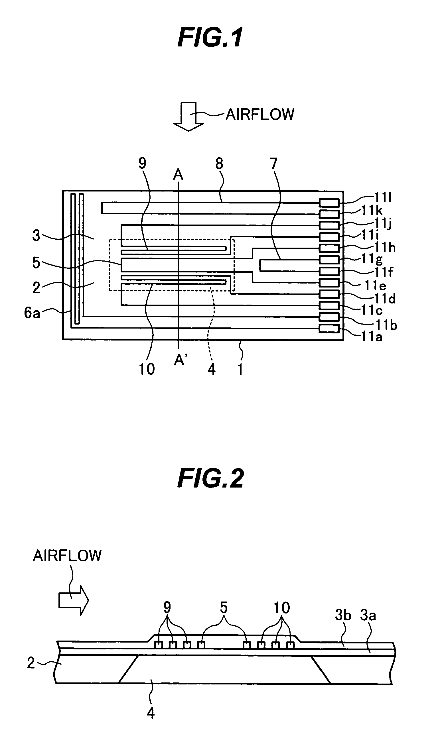
[0041]FIG. 1 is a plan view showing a measuring element of a thermal air flowmeter according to the present invention. FIG. 2 is a sectional view of the measuring element taken along the line A-A′ in FIG. 1.

[0042]Referring to FIGS. 1 and 2, a measuring element 1 comprises a semiconductor substrate 2 made of, e.g., silicon and having a cavity 4 formed by anisotropic etching to extend upward from a lower surface of the substrate to a boundary with respect to an electric insulating film 3a, and a heating resistor 5 formed on the electric insulating film 3a that covers the cavity 4. The measuring element 1 further comprises a temperature compensation resistor 6a for performing temperature compensation of the heating resistor 5, a first resistor 7, and a second resistor 8, the first and second resistors forming a bridge circuit in combination with the heating resistor 5 and the temperature compensation resistor 6a.

[0043]On the measuring element 1, a first temperature measuring resistor ...

second embodiment

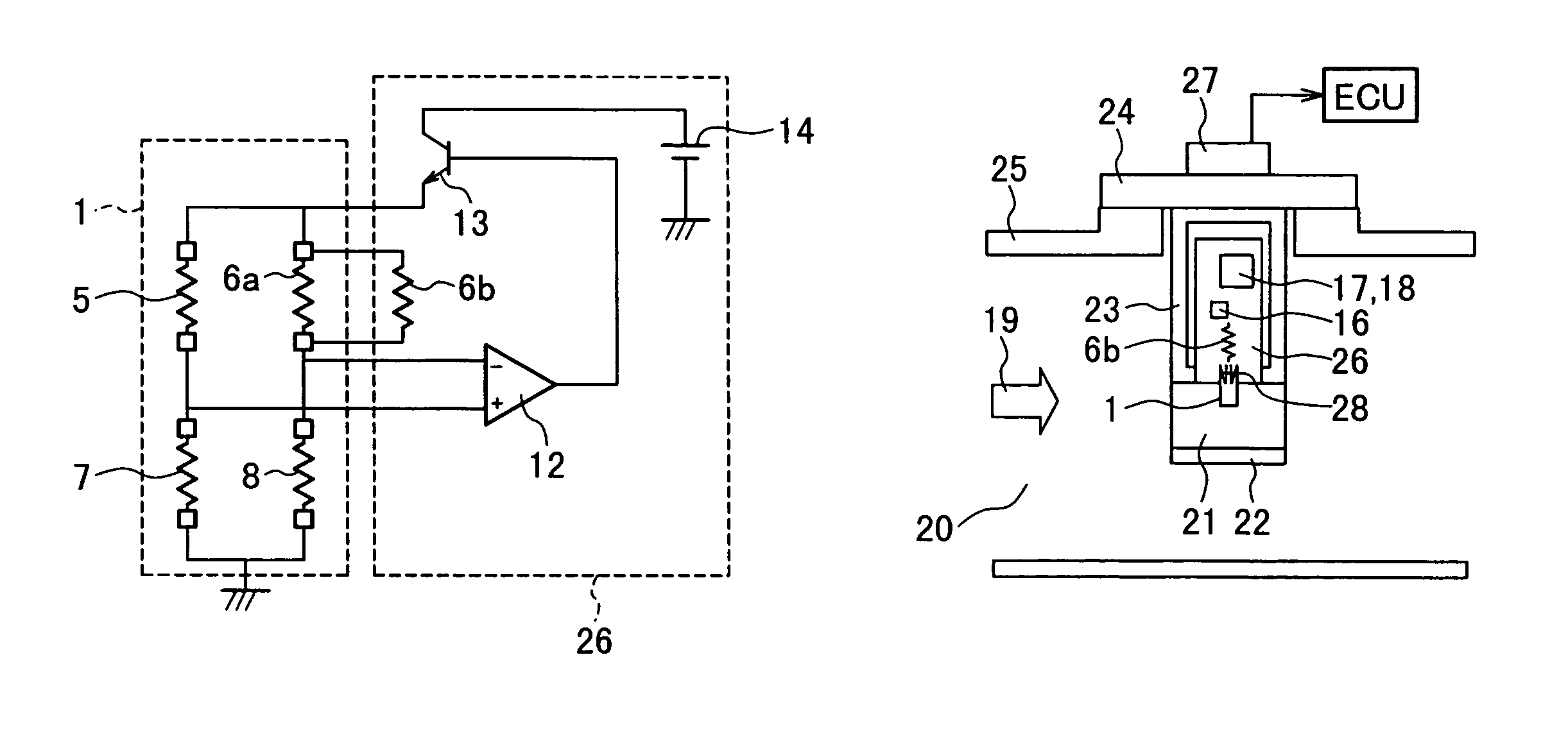
[0101]FIG. 15 is a diagram showing a drive circuit for the heating resistor 5 in the present invention. This drive circuit supplies a current to the heating resistor 5 on the measuring element 1 and performs heating temperature control.

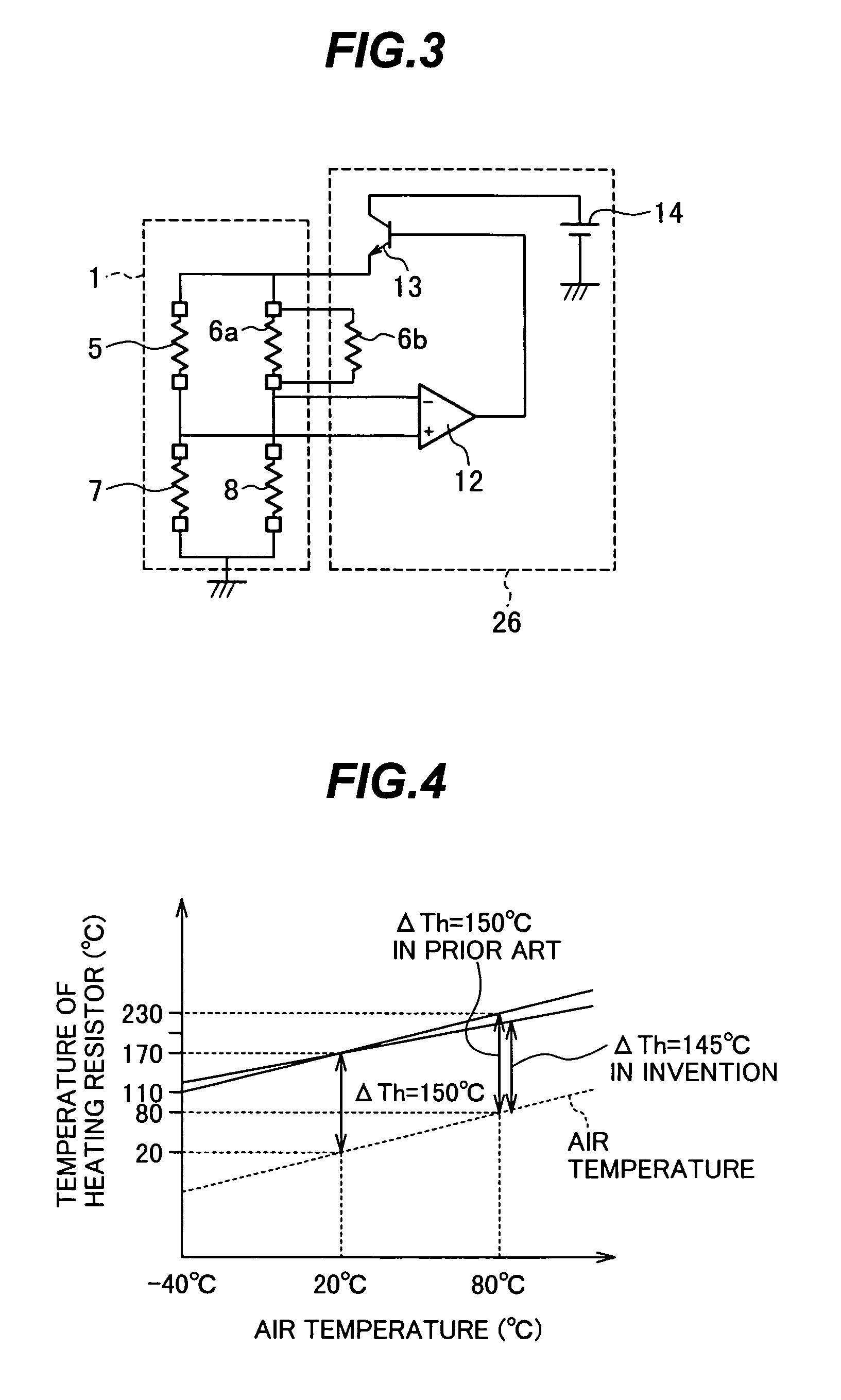
[0102]The drive circuit shown in FIG. 15 differs from the drive circuit shown in FIG. 3 in that the resistor 6b is connected to the resistor 6a in parallel in the example of FIG. 3, while a resistor 29 is connected to the resistor 7 in parallel in the example of FIG. 15 instead of connecting the resistor 6b to the resistor 6a. The other arrangement in the example of FIG. 15 is the same as that in the example of FIG. 3.

[0103]Referring to FIG. 15, the heating resistor 5, the temperature compensation resistor 6a, the first resistor 7, and the second resistor 8, which are formed on the measuring element 1, are all made of the same resistor material, while the fixed resistor 29 is made of a different resistor material from that used for the resistors 5, 6a...

third embodiment

[0107]FIG. 16 is a diagram showing a flow rate detection circuit according to the present invention.

[0108]Referring to FIG. 16, the flow rate detection circuit comprises a first temperature measuring resistor 9 for detecting the flow rate, a second temperature measuring resistor 10 connected to the first temperature measuring resistor 9 in series, the first and second temperature measuring resistors 9, 10 being made of the same resistor material (polysilicon resistor), and a fixed resistor 30 connected to the resistor 10 in parallel and made of a material (having the resistance temperature coefficient=about 0 ppm / ° C.) different from that of the resistors 9 and 10. The fixed resistor 30 may be connected to the second temperature measuring resistor 10 in series.

[0109]FIG. 17 is a graph showing dependency of a flow rate detection voltage upon the air temperature at a flow rate of 0 kg / h.

[0110]As shown in FIG. 17, because the flow rate detection circuit of the prior art is a serial cir...


PUM


Abstract

A thermal air flowmeter having excellent temperature characteristics and improved measurement accuracy. The thermal air flowmeter includes a temperature sensor disposed in a casing of the air flowmeter, a computing unit for correcting a flow rate detection voltage from a measuring element by using the temperature sensor, and a heating temperature control disposed in a temperature control circuit for performing temperature control of a heating resistor to vary a temperature rise of the heating resistor relative to an air temperature depending on the air temperature. Flow rate detection errors of the thermal air flowmeter caused by an overall temperature change and a temperature change on an intake passage wall surface can be corrected simultaneously and a thermal air flowmeter having superior measurement accuracy can be realized.

Description

TECHNICAL FIELD[0001]The present invention relates to a thermal flowmeter of a fluid, and more particularly to a thermal flowmeter of a fluid suitable for measuring an intake air amount in an internal combustion engine.BACKGROUND ART[0002]As one example of fluid flowmeters, there is an air flowmeter disposed in an electronically controlled fuel injector of an internal combustion engine for an automobile, for example, to measure an intake air amount. Such an air flowmeter is mainly practiced in the thermal type because of a capability of directly detecting a mass flow rate.[0003]Among thermal air flowmeters, particularly a thermal air flowmeter employing a measuring element manufactured by the semiconductor micromachining technology has received attention for the reasons that it can be manufactured at a reduced cost and can be driven with lower power.[0004]One known thermal air flowmeter using a semiconductor substrate is disclosed in JP,A 2002-310762. The technique disclosed in that...

Claims


Application Information

Patent Timeline
Patent Type & Authority Patents(United States)
IPC IPC(8): G01F1/68G01F1/00G01F1/684G01F1/696
CPCG01F1/6965G01F1/6845
Inventor NAKANO, HIROSHIYAMADA, MASAMICHIMATSUMOTO, MASAHIROWATANABE, IZUMIHANZAWA, KEIJINAKADA, KEIICHI
Owner HITACHI LTD
Why Eureka
Try Eureka