
High-side current sense circuit with common-mode voltage reduction

a current sense circuit and high-side technology, applied in the direction of electric variable regulation, process and machine control, instruments, etc., can solve the problems of non-zero dc voltage component and some current measurement circuits

Active Publication Date: 2009-12-15
ANALOG DEVICES INC
View PDF10 Cites 12 Cited by
  • Summary
  • Abstract
  • Description
  • Claims
  • Application Information

AI Technical Summary

Benefits of technology

The present invention provides a high-side current sense circuit that reduces the impact of common-mode voltage on the gain stage's output voltage and measured current value. The circuit includes a sense resistor and a voltage modification circuit to keep the common mode voltage within the input of the gain stage. The circuit also includes a differential gain stage powered by supply voltages and produces an output voltage that varies with the difference between its input signals. The voltage modification circuit ensures that the output voltage of the gain stage is proportional to the current being measured. The technical effect of this invention is to provide a more accurate and reliable current sensing circuit for high-side applications.

Problems solved by technology

When measuring a high-side current, the signal of interest has a non-zero DC voltage component which can prove problematic for some current measurement circuits.

Method used


Image

  • High-side current sense circuit with common-mode voltage reduction
  • High-side current sense circuit with common-mode voltage reduction
  • High-side current sense circuit with common-mode voltage reduction

Examples


Embodiment Construction

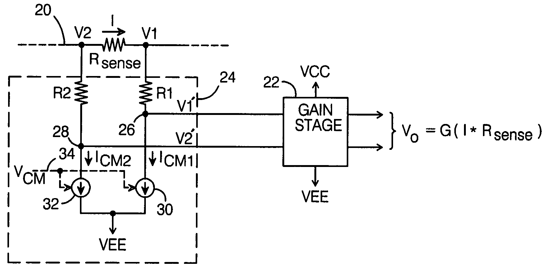
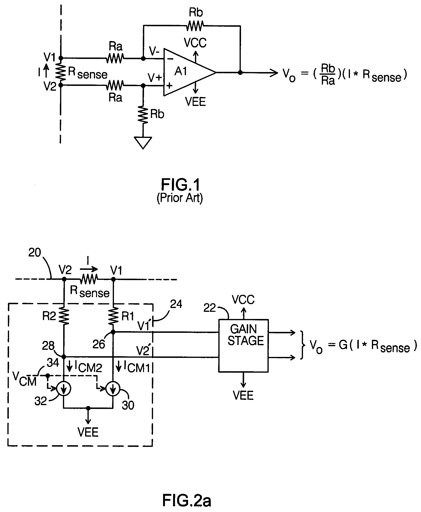
[0019]The present invention is for use with a sensing element having a resistance Rsense, which conducts a current (I) to be measured. The present current sense circuit provides a means for measuring differential voltage I*Rsense when the common mode portion of the voltages across Rsense are above or below the power rails of the measuring circuit, while having a minimal effect on the measured voltage. This is accomplished by adding or subtracting a common mode voltage from both of the voltages across Rsense.

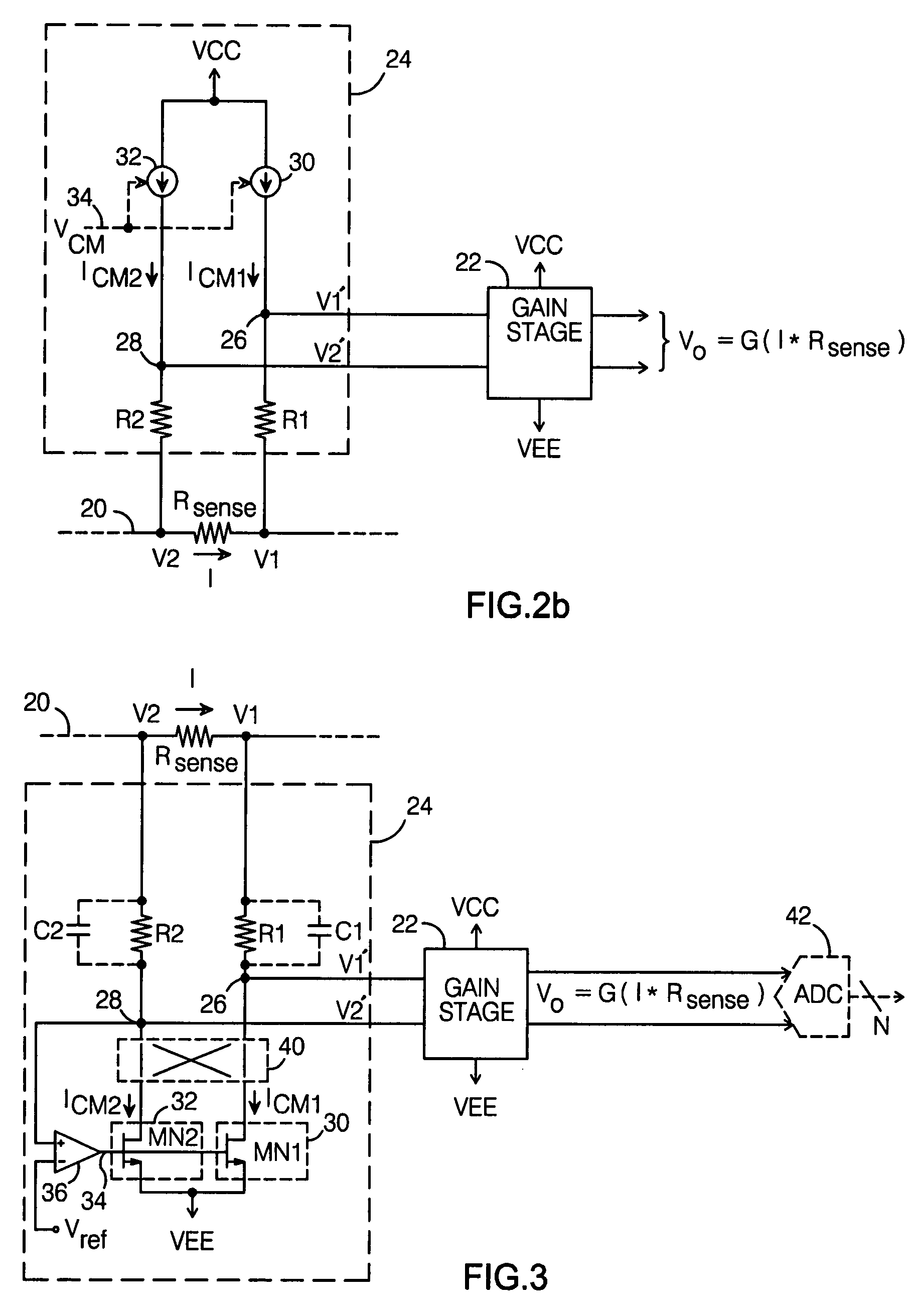
[0020]One way in which this may be accomplished is shown in FIG. 2. As before, a sense resistor with resistance Rsense is connected in series with a signal 20 such that it conducts the signal's current I, causing voltages V2 and V1 to develop on either side of Rsense. A differential gain stage 22 is powered by first and second supply voltages VCC and VEE (such that VCC>VEE; VEE may be at ground potential), and is arranged to produce an output Vo which varies with the difference b...


PUM


Abstract

A high-side current sense circuit comprises a sense resistance Rsense connected in series with a signal having an associated current to be measured I, which develops voltages V1 and V2 on either side of Rsense. A differential gain stage powered by supply voltages VCC and VEE produces an output voltage which varies with the difference between its input signals. To keep the common mode portion of the input signal between voltages VCC and VEE, a voltage modification circuit subtracts or adds a common mode voltage to or from V1 and V2 to produce modified voltages V1′ and V2′, which are coupled to the gain stage inputs. The voltage modification circuit is arranged to ensure that VEE≦V1′ and V2′≦VCC.

Description

BACKGROUND OF THE INVENTION[0001]1. Field of the Invention[0002]This invention relates generally to the field of current sense circuits, and more particularly to high-side current sense circuits.[0003]2. Description of the Related Art[0004]There are numerous applications in which it is necessary to measure a particular current in a circuit. For example, it is often desirable to know the current consumed by a circuit. This could be determined by sensing the current on the “high-side” of the circuit—i.e., where a non-zero supply voltage is connected to the circuit, or on the circuit's “low-side”—i.e., where the current returns to its source.[0005]When measuring a high-side current, the signal of interest has a non-zero DC voltage component which can prove problematic for some current measurement circuits. An example of this is illustrated with the circuit shown in FIG. 1, which measures the current using a sense resistor having a resistance Rsense connected in series with the signal w...

Claims


Application Information

Patent Timeline
Patent Type & Authority Patents(United States)
IPC IPC(8): G01R19/00
CPCG05F5/00
Inventor MIRANDA, EVALDO M.BAKKER, ANTHONIUS
Owner ANALOG DEVICES INC
Learn More