Optical element package

a technology of optical elements and packaging bodies, applied in the direction of transportation and packaging, mechanical equipment, instruments, etc., can solve the problems of large area of illuminating devices, easy generation of wrinkles, deflections, warpages, etc., and achieve the effect of not uniformly generating deformation of optical sheets due to hea

Inactive Publication Date: 2009-12-15
SONY CORP
View PDF10 Cites 2 Cited by
  • Summary
  • Abstract
  • Description
  • Claims
  • Application Information

AI Technical Summary

Benefits of technology

[0007]In recent years, as the display unit has a large-sized screen, the area of the illuminating device becomes large. In this case, the area of various optical sheets such as the prism sheet and the diffusion plate needs to be larger. However, when these optical sheets have a larger area, a wrinkle, deflection, and warpage are easily generated due to the own weight. In addition, along with the large area thereof, the illuminance of the light source to retain lightness of the display surface is increased. Thus, heat applied to the surface of the optical sheet with a larger area is also increased. Since the heat is ununiformly transferred to the surface of the optical sheet, deformation of the optical sheet due to the heat is not uniformly generated. In the result, a wrinkle, deflection, and warpage are easily generated due to the heat as well.
[0008]Meanwhile, as a method to prevent such generation of the wrinkle, deflection, and warpage of the optical sheet associated with the large-sized screen, for example, lack of rigidity may be improved by thickening the optical sheet. However, in this case, the illuminating device is thickened and thereby realizing the thin illuminating device is inhibited. Accordingly, as described in Japanese Unexamined Patent Application Publication No. 2005-301147, whole areas of optical sheets may be bonded with each other by using a transparent adhesive in the order of lamination. When the optical sheets are layered with the transparent adhesive in between as above, the rigidity of the optical sheet may be improved, and generation of the wrinkle, deflection, and warpage may be prevented.
[0026]According to the optical packaged body, the illuminating device, and the display unit of the invention, the support medium is covered with the packaging film in a state being applied with shrinkage force. Thus, even if the packaging film is thinned, generation of a wrinkle, deflection, and warpage may be prevented in at least the foregoing first region and the foregoing second region in the packaging film. Thereby, in the case that the optical function section that acts on the light from the light source is provided in at least one of the foregoing first region and the foregoing second region in the packaging film packaging the support medium, even if the thickness of the packaging film is thin such as about several 10 μm, there is no possibility that a wrinkle, deflection, and warpage are generated in the optical function section. In the result, the optical function section provided in at least one of the foregoing first region and the foregoing second region in the packaging film may be used instead of an optical sheet having a function similar to that of the optical function section. In addition, compared to a case that the optical sheet having a function similar to that of the optical function section is provided in the packaging film, the thickness of the entire optical packaged body may be reduced. Accordingly, in the invention, while generation of a wrinkle, deflection, and warpage is prevented, the thickness of the optical packaged body may be reduced.
[0027]According to the first and the second methods of manufacturing an optical packaged body of the invention, the support medium is covered with the first resin film and the second resin film in a state being applied with shrinkage force. Thus, even if the first resin film and the second resin film are thinned, generation of a wrinkle, deflection, and warpage may be prevented in at least a region where the first resin film and the second resin film are opposed to the support medium in the first resin film and the second resin film. Thereby, in the case that the optical function section that acts on the light from the light source is provided in a region where at least one of the first resin film and the second resin film is opposed to the support medium in the first resin film and the second resin film packaging the support medium, even if the thickness of the first resin film and the second resin film is thin such as about several 10 μm, there is no possibility that a wrinkle, deflection, and warpage are generated in the optical function section. In the result, the optical function section provided in at least the region where the first resin film and the second resin film are opposed to the support medium in the first resin film and the second resin film may be used instead of an optical sheet having a function similar to that of the optical function section. In addition, compared to a case that the optical sheet having a function similar to that of the optical function section is provided between the first resin film and the second resin film, the thickness of the entire optical packaged body may be reduced. Accordingly, in the invention, while generation of a wrinkle, deflection, and warpage is prevented, the thickness of the optical packaged body may be reduced.

Problems solved by technology

In recent years, as the display unit has a large-sized screen, the area of the illuminating device becomes large.
However, when these optical sheets have a larger area, a wrinkle, deflection, and warpage are easily generated due to the own weight.
Since the heat is ununiformly transferred to the surface of the optical sheet, deformation of the optical sheet due to the heat is not uniformly generated.
In the result, a wrinkle, deflection, and warpage are easily generated due to the heat as well.
However, in this case, the illuminating device is thickened and thereby realizing the thin illuminating device is inhibited.
However, in the structure in which the optical sheets are simply bonded with each other with the transparent adhesive in between, the thickness of the illuminating device is increased by the thickness portion of the transparent adhesive, and thereby realizing the thin illuminating device may be inhibited.
When each optical sheet is expanded and shrunk repeatedly and the optical sheets are adhered to each other, there is a possibility that deflection and warpage may be generated in the optical sheet and thus the optical characteristics deteriorate.
However, when the diffusion plate and the all optical sheets are simply covered with the transparent packaging film, generation of the wrinkle, deflection, and warpage due to heat or the like is not sufficiently decreased.
Further, there is a possibility that a wrinkle is generated in the packaging film itself and thus the optical characteristics are deteriorated.

Method used


Image

  • Optical element package
  • Optical element package
  • Optical element package

Examples


first embodiment

Modification of First Embodiment

[0097]In the foregoing embodiment, the packaging film 20 covers the diffusion plate 11 as the support medium. However, the packaging film 20 may cover other support medium. As other support medium, for example, a transparent plate such as plastic and glass, an optical plate to change light characteristics of light emitted from the light source by providing diffusion, light collection and the like are cited. As the optical plate, for example, a wave plate, a reflective polarizing plate, a prism plate having a concave and convex shape such as a prism or the like is cited. To function as a support medium, the thickness thereof is preferably in the range about from 1000 μm to 10000 μm. Above the light source of a direct-lighting liquid crystal display unit, a resin plate including a diffusion filler being about 1 mm to 4 mm thick having a diagonal diameter of about 2 inches to 100 inches, a diffusion optical plate having a layer provided with a shape as a...

second embodiment

Modification of Second Embodiment

[0111]In the foregoing embodiment, the description has been given of the case that the stack 10 in which the diffusion plate 11, the diffusion sheet 12, the lens film 13, and the reflective polarizing sheet 14 are sequentially layered from the light source image segmentation section 23 side is covered with the packaging film 20 as an example. However, it is possible that an optical sheet having a diffusion function (for example, an optical sheet similar to the diffusion sheet 12) is arranged instead of the reflective polarizing sheet 14.

Third Embodiment

[0112]Next, a description will be given of a third embodiment of the invention.

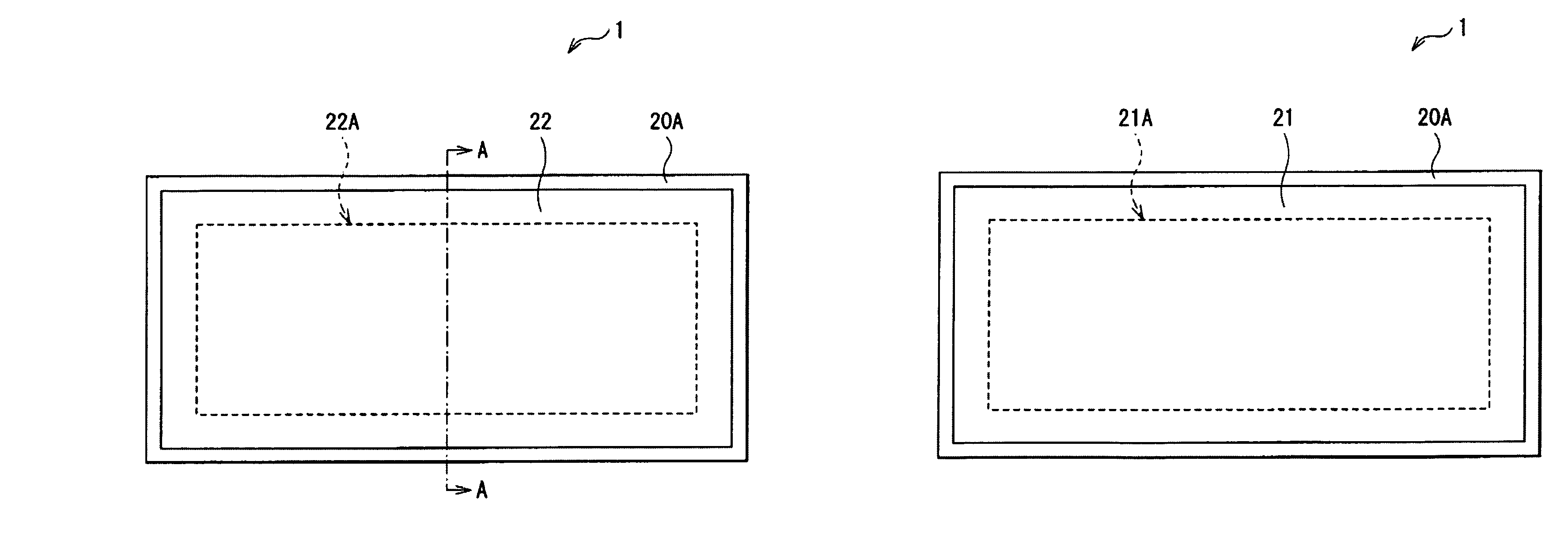
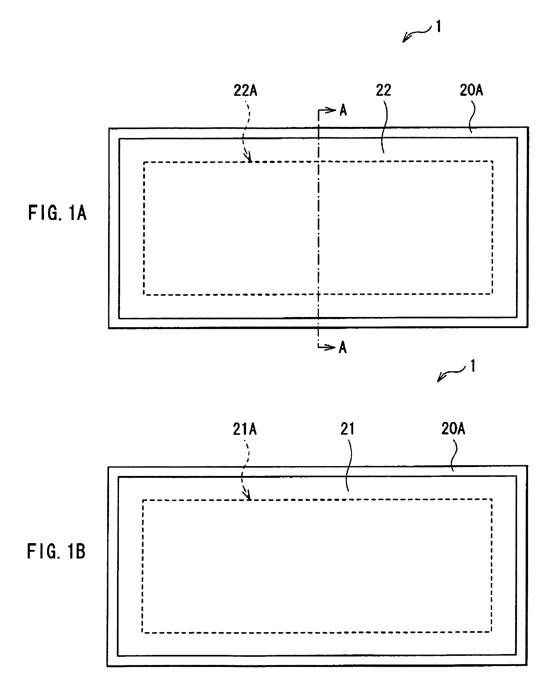
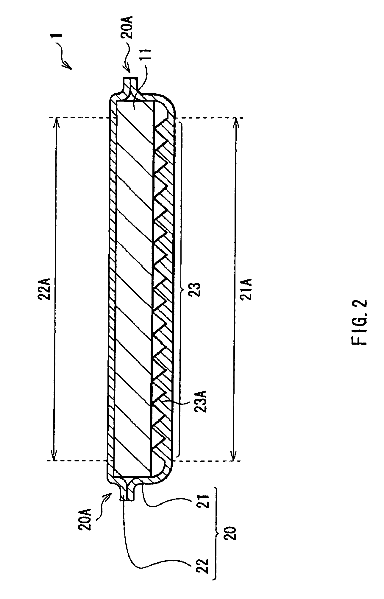
[0113]FIG. 4A shows an example of a top face structure of an optical packaged body 3 according to the third embodiment of the invention. FIG. 4B shows an example of a bottom face structure of the optical packaged body 3 of FIG. 4A. FIG. 5 shows an example of a cross sectional structure taken along arrow A-A of the optical pa...

third embodiment

Modification of Third Embodiment

[0149]In the foregoing embodiment, the description has been given of the case that the stack 10 in which the light source image segmentation sheet 15, the diffusion plate 11, and the diffusion sheet 12 are sequentially layered toward the polarization split section 24 is covered with the packaging film 20 as an example. However, for example, as shown in FIG. 12, the lens film 13 may be arranged between the diffusion sheet 12 and the polarization split section 24. At this time, each convex section 13A of the lens film 13 preferably extends in the short direction of the diffusion plate 11 (direction orthogonal to the extending direction of the convex section 15A of the light source image segmentation sheet 15 and the convex section 24A of the polarization split section 24). Further, in the foregoing embodiment, the description has been given of the case that each convex section 24A extends in the extending direction of the convex section 15A as an exampl...


PUM

PropertyMeasurementUnit
thicknessaaaaaaaaaa
thicknessaaaaaaaaaa
thickaaaaaaaaaa

Abstract

An optical packaged body capable of preventing generation of a wrinkle, deflection, and warpage, capable of being thinned is provided. The optical package body includes a support medium and a packaging film that covers the support medium in a state of being applied with shrinkage force. The packaging film has an optical function section that acts on light from a light source in at least one of a first region into which the light from the light source enters and a second region from which the light from the light source is emitted after passing through the optical packaged body when the light source is arranged on one face side of the optical packaged body.

Description

CROSS REFERENCES TO RELATED APPLICATIONS[0001]The present invention contains subject matters related to Japanese Patent Application No. 2007-032766 filed in the Japanese Patent Office on Feb. 13, 2007, Japanese Patent Application No. 2007-246237 filed in the Japanese Patent Office on Sep. 21, 2007, and Japanese Patent Application No. 2007-341237 filed in the Japanese Patent Office on Dec. 28, 2007, the entire contents of which being incorporated herein by reference.BACKGROUND OF THE INVENTION[0002]1. Field of the Invention[0003]The present invention relates to a light-transmissive optical packaged body, a method of manufacturing it, an illuminating device including it, and a display unit including it.[0004]2. Description of the Related Art[0005]As a display unit of a word processor, a laptop personal computer and the like, a liquid crystal display unit including a thin and easily viewable backlight (illuminating device) has long been used. The illuminating devices for a liquid cryst...

Claims


Application Information

Patent Timeline
Patent Type & Authority Patents(United States)
IPC IPC(8): G02B27/10
CPCG02B5/045G02B6/0053G02B6/0065G02F1/133611G02B5/02G02F1/133604Y10T428/1328G02F1/133608G02F2001/133607G02F2201/54G02F1/133606G02B27/285G02F1/133607G02B6/0001G02F1/1335
Inventor OHTA, EIJIABIKO, TORUKUDO, YASUYUKIODAGIRI, HIROKAZUSATO, SATOSHIYU, ANDREW CHAKCHUNGSHINKAI, SHOGOOMURA, TAROMIZUNO, HIROSHIHORII, AKIHIROHARIMA, TATSUYA
Owner SONY CORP
Why Eureka
Try Eureka