
Parallel pneumatic gripper

a pneumatic gripper and parallel technology, applied in the field of grippers, can solve the problems of rapid wear and allow the development of high blocking power, and achieve the effects of reducing joining wear, improving the functionality and performance of the device, and improving the joining condition

Inactive Publication Date: 2009-12-22
GIMATIC SRL
View PDF13 Cites 8 Cited by
  • Summary
  • Abstract
  • Description
  • Claims
  • Application Information

AI Technical Summary

Benefits of technology

[0007]Another object of the invention is to allow, sizes of the gripper being equal, increased strokes and a variation in the stroke of the jaws.
[0008]Yet another object is therefore to provide a pneumatic gripper with improved joining conditions between the control piston and the jaw it drives by means of an oscillating lever, in order to improve the functionality and performance of the device, to reduce joining wear and increase the grip and blocking forces on the items to be handled.
[0009]A further object of the invention is to propose and provide a pneumatic gripper with simpler and less costly jaws and at the same time which have greater precision in matching with the gripper body.

Problems solved by technology

In fact, in said grippers, the connection lever of the piston to one of the jaws is flat and has rather limited contact surfaces with the joint pins and with the oscillation pin, consequently subject to rapid wear and such as not to allow the development of high blocking power.

Method used


Image

  • Parallel pneumatic gripper
  • Parallel pneumatic gripper
  • Parallel pneumatic gripper

Examples


Embodiment Construction

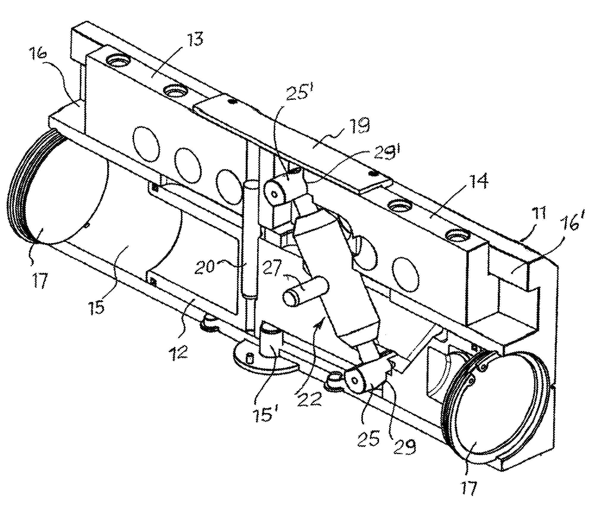
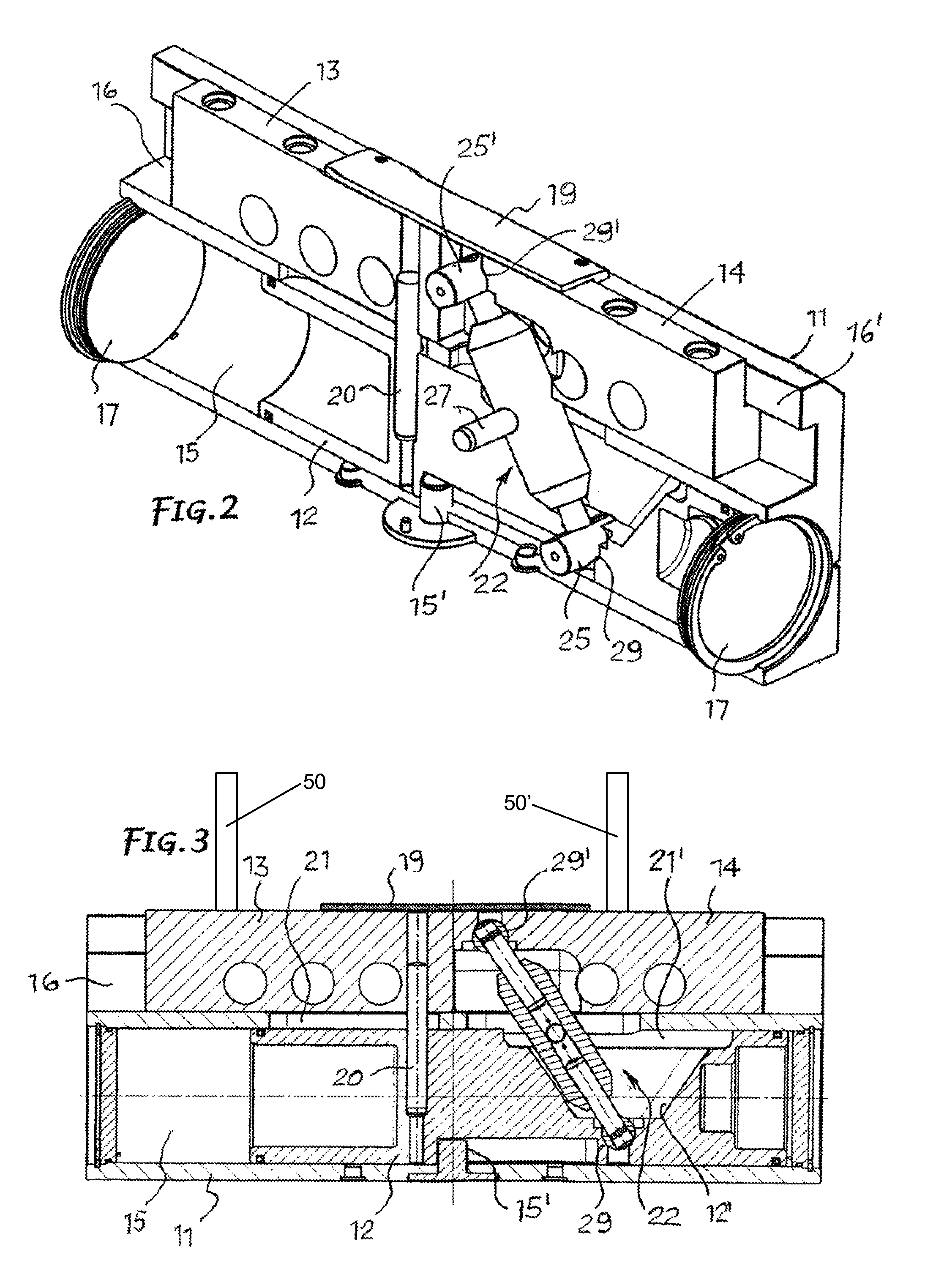
[0020]As shown, the parallel pneumatic gripper comprises fundamentally a gripper body 11, an alternate pneumatic piston 12 and two aligned jaws 13, 14 holding an equal number of shoes 50, 50′ configured for gripping and release of an article.

[0021]Longitudinally, the gripper body forms a cylindrical chamber 15 and a guide 16 parallel to each other. The opposite ends of the cylindrical chamber 15 are closed by flanges 17. The pneumatic piston 12 is guided and movable in said chamber 15 by alternate motion for a stroke that can be limited by a stop 15′. It is driven by a fluid under pressure delivered to and discharged from said chamber 15 from opposite sides of the piston through inlet / outlet holes 18, 18′ connected to conduits for the circulation of said fluid.

[0022]Jaws 13, 14 are housed in the guide 16 formed in the gripper body 11 and are movable linearly in opposite directions by means of the piston 12. In particular, said guide 16 can be an upside-down T shape and jaws 13, 14 c...


PUM


Abstract

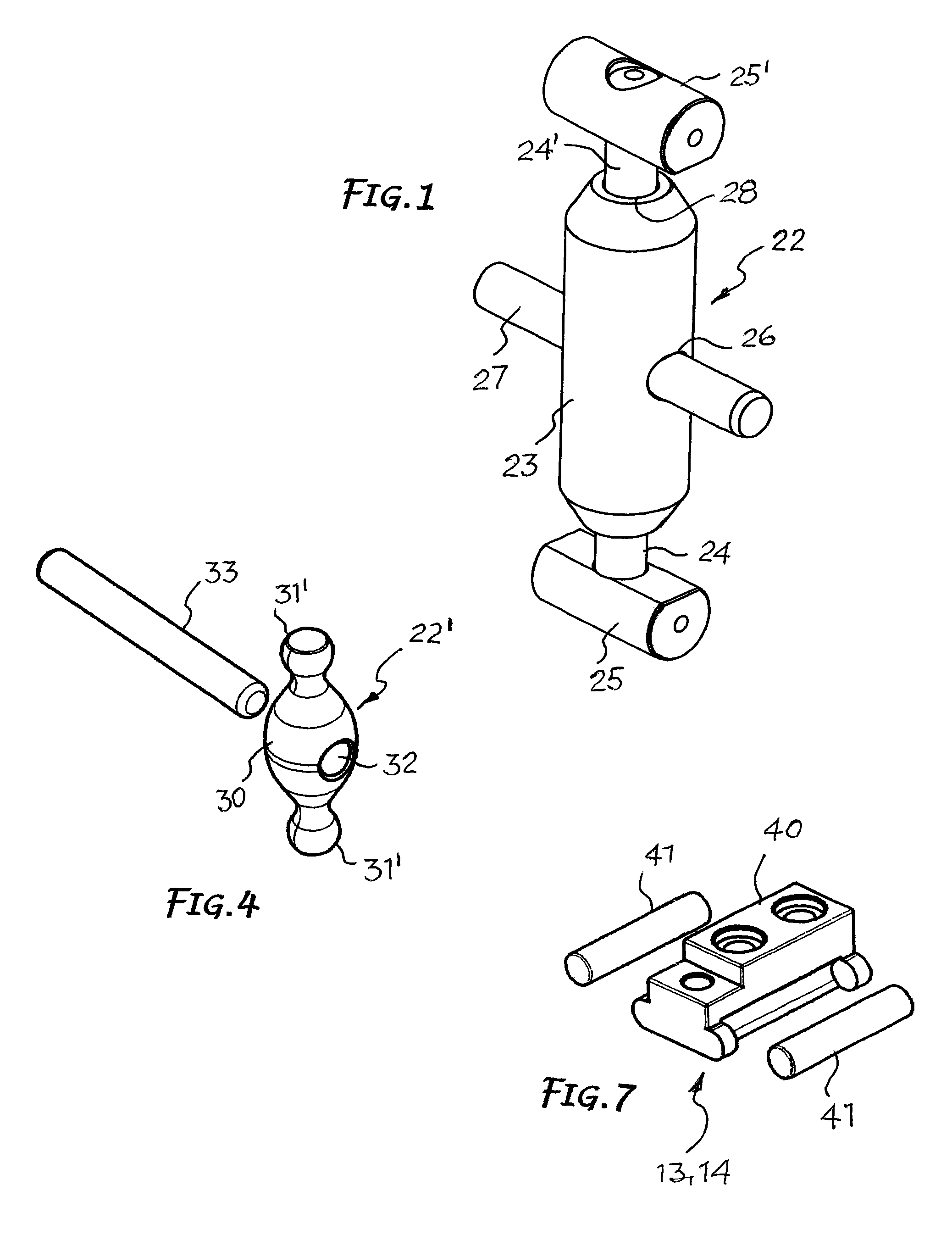
The invention concerns a parallel pneumatic gripper which includes a gripper body (11) forming a chamber (15), an alternate pneumatic piston (12) movable in the chamber, and two jaws (13, 14) controlled by the piston and movable in opposite directions. A first jaw (13) is rigidly attached to the piston (12) to follow its movements, whereas the second jaw (14) is connected to the piston (12) by an oscillating transmission element or lever (22, 22′) comprising an intermediate larger dimensioned cross section portion (23, 30) having a transversal bore to house the oscillating central fulcrum and two terminal heads with rolling surfaces (25, 25′; 31, 31′) designed to couple with corresponding seats provided respectively on the bottom of a flaring shaped in one side of the piston (12) and in the second jaw (14).

Description

FIELD OF THE INVENTION[0001]This invention concerns in general grippers for gripping and handling pieces, and refers in particular to a parallel pneumatic gripper.STATE OF THE ART[0002]Pneumatic grippers of the types described in a previous U.S. Pat. No. 6,273,485 by the same applicant are already known and correspond to the preamble of claim 1. They are made up fundamentally of a body forming a chamber closed at the opposite ends by two flanges, an alternate pneumatic piston moving in said chamber, and two jaws guided linearly in a housing formed in said body parallel to said chamber, controlled by said piston and provided with means for gripping and releasing the items to be handled.[0003]The two jaws are moved in opposite directions to each other by the piston. A first jaw is rigidly attached directly to the same piston, whereas the second jaw is connected to the piston by means of a drive lever which oscillates on a central oscillating pin supported in the gripper body and joine...

Claims


Application Information

Patent Timeline
Patent Type & Authority Patents(United States)
IPC IPC(8): B25J15/08
CPCB25J15/0266
Inventor MAFFEIS, GIUSEPPE
Owner GIMATIC SRL
Learn More