Parallel pneumatic gripper
- Summary
- Abstract
- Description
- Claims
- Application Information
AI Technical Summary
Benefits of technology
Problems solved by technology
Method used
Image
Examples
Embodiment Construction
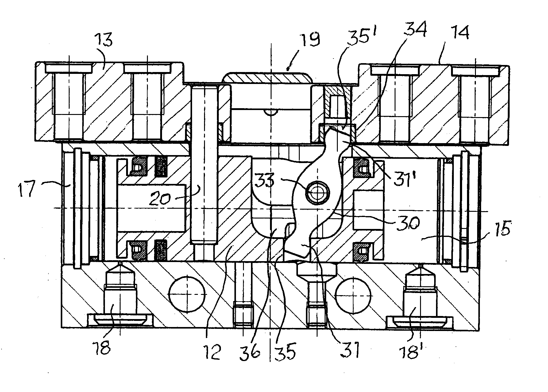
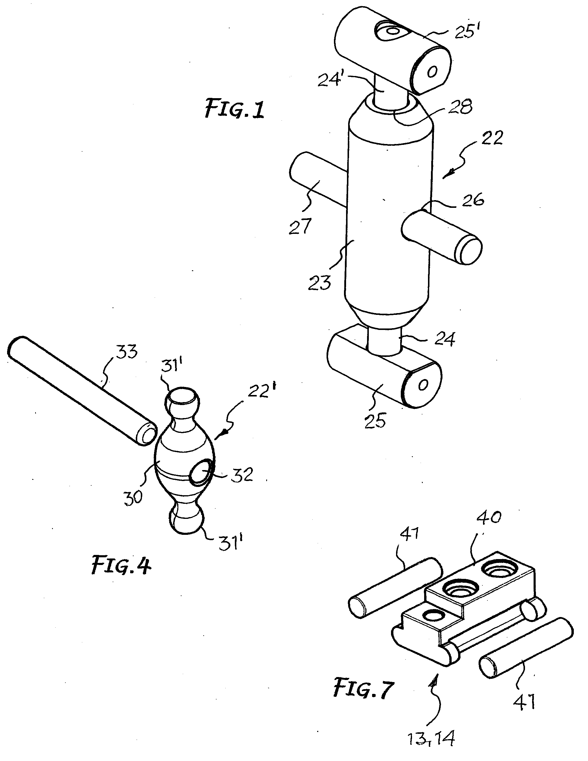
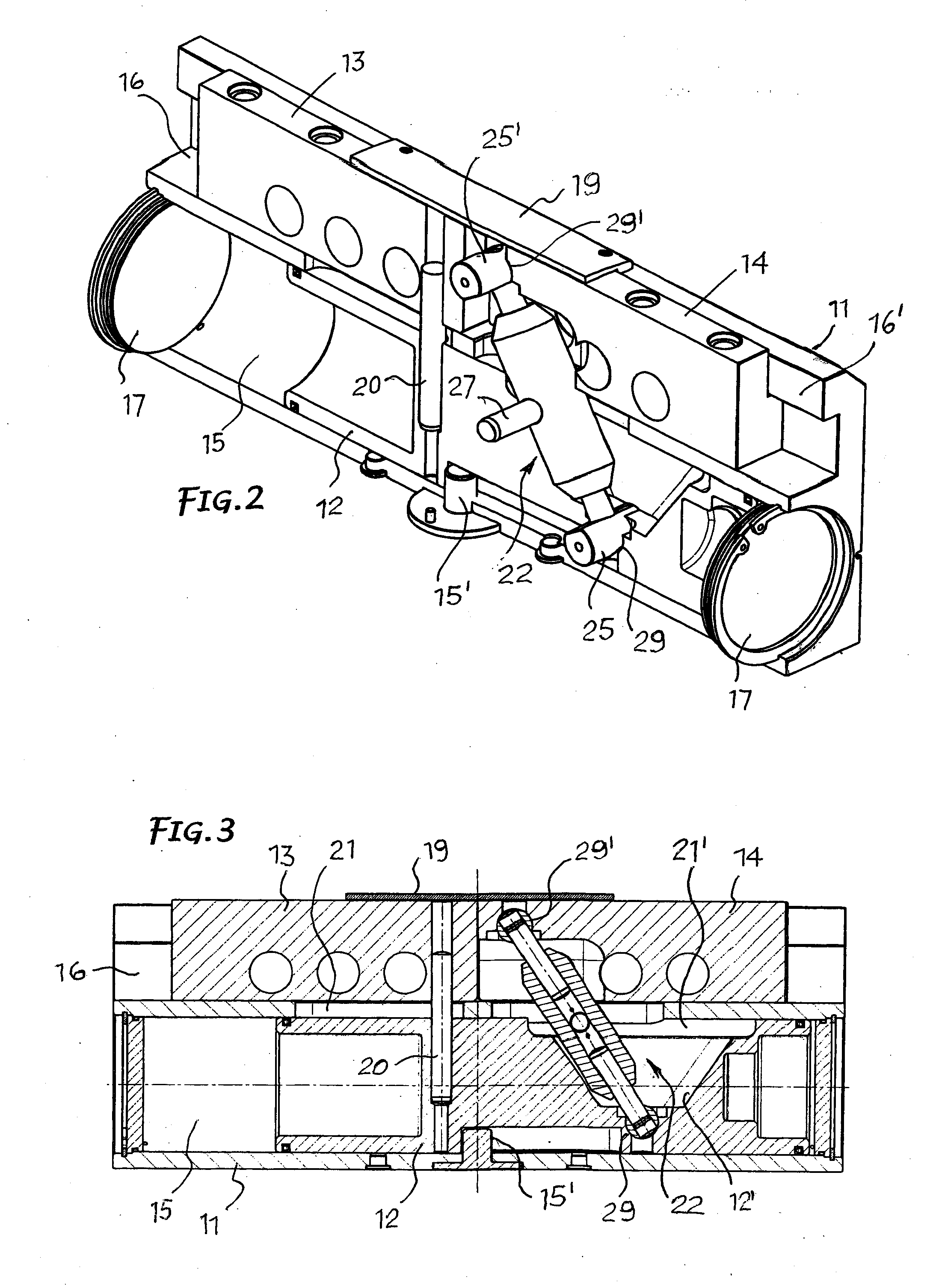
[0020] As shown, the parallel pneumatic gripper comprises fundamentally a gripper body 11, an alternate pneumatic piston 12 and two aligned jaws 13, 14 holding an equal number of shoes—not shown—configured for gripping and release of an article.
[0021] Longitudinally, the gripper body forms a cylindrical chamber 15 and a guide 16 parallel to each other. The opposite ends of the cylindrical chamber 15 are closed by flanges 17. The pneumatic piston 12 is guided and movable in said chamber 15 by alternate motion for a stroke that can be limited by a stop 15′. It is driven by a fluid under pressure delivered to and discharged from said chamber 15 from opposite sides of the piston through inlet / outlet holes 18, 18′ connected to conduits for the circulation of said fluid.
[0022] Jaws 13, 14 are housed in the guide 16 formed in the gripper body 11 and are movable linearly in opposite directions by means of the piston 12. In particular, said guide 16 can be an upside-down T shape and jaws 1...
PUM
 Abstract
Description
Claims
Application Information
 - R&D
- Intellectual Property
- Life Sciences
- Materials
- Tech Scout
- Unparalleled Data Quality
- Higher Quality Content
- 60% Fewer Hallucinations
Browse by: Latest US Patents, China's latest patents, Technical Efficacy Thesaurus, Application Domain, Technology Topic, Popular Technical Reports.
© 2025 PatSnap. All rights reserved.Legal|Privacy policy|Modern Slavery Act Transparency Statement|Sitemap|About US| Contact US: help@patsnap.com


