
Wireless charging test bench for electric vehicle

A test bench, wireless charging technology, applied in vehicle testing, machine/structural component testing, electrical measurement, etc., can solve problems such as low work efficiency, low test efficiency, and low test coverage of wireless charging systems, and achieve The effect of increasing the test distance and reducing the size

Pending Publication Date: 2020-04-10
无锡市沃乐思科技有限公司 +1
View PDF0 Cites 6 Cited by
  • Summary
  • Abstract
  • Description
  • Claims
  • Application Information

AI Technical Summary

Problems solved by technology

[0003] The test plan of the traditional wireless charging system mainly uses discrete instruments for measurement. In order to test the efficiency of the wireless charging system under the alignment and misalignment of the transmitting coil and the receiving coil, the relative position of the coils is manually adjusted, and then the wireless charging process is tested. This method is not only inefficient, but also cannot realize the development and testing of some advanced charging (or testing) control programs that require real-time control of the coil position (or speed), and the test coverage of the wireless charging system is small. Test efficiency Low

Method used


Image

  • Wireless charging test bench for electric vehicle
  • Wireless charging test bench for electric vehicle
  • Wireless charging test bench for electric vehicle

Examples


Embodiment Construction

[0023] The technical solutions of the present invention will be further described below in conjunction with the accompanying drawings and specific embodiments.

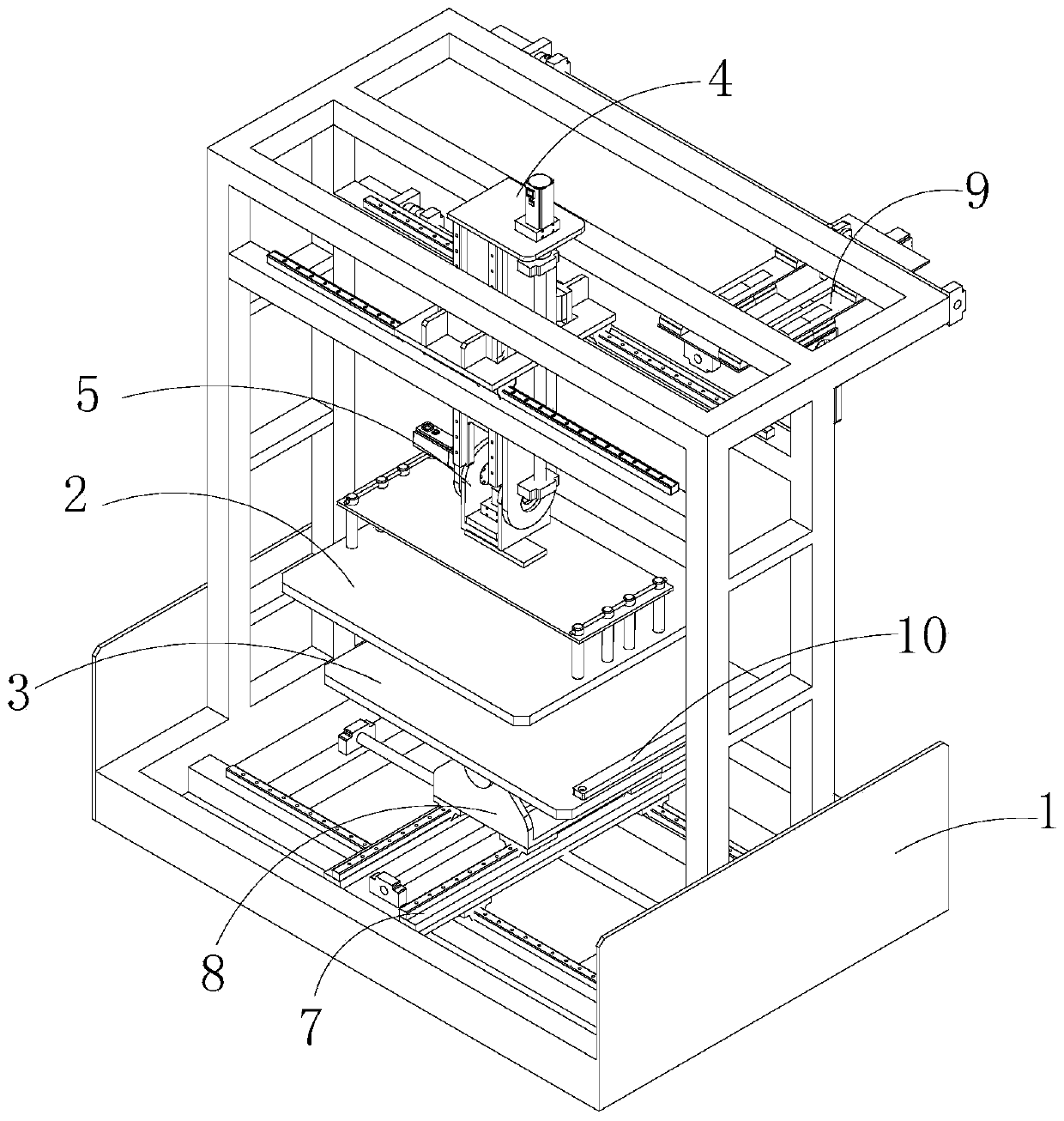
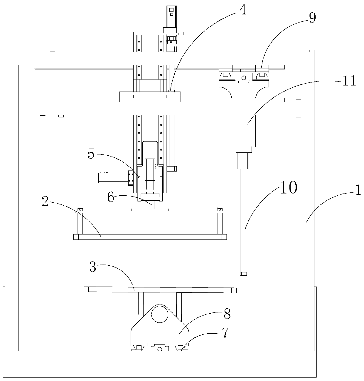
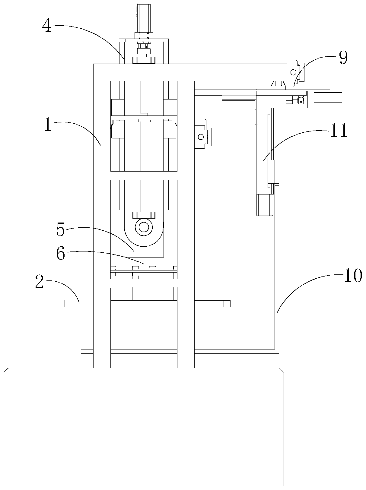
[0024] An electric vehicle wireless charging test bench, the test bench includes a frame 1, an upper plate 2 and a lower plate 3 installed on the frame 1, the lower plate 3 is used to place a transmitting coil, and the upper plate 2 is located on the lower plate 3 The upper part is used to place the receiving coil. Both the lower plate 3 and the upper plate 2 are made of non-metallic insulating materials, and both the upper plate 2 and the lower plate 3 can be installed on the frame 1 by sliding along the X-axis direction; Among the flat plate 2 and the lower plate 3, at least one of them can slide along the Y-axis direction, at least one of them can be lifted along the Z-axis direction, and at least one of them can rotate around its own vertical centerline, and it is installed on the frame 1 , in both the upper plate...


PUM


Abstract

The invention discloses a wireless charging test bench for an electric vehicle. The test bench comprises a rack, an upper flat plate and a lower flat plate which are mounted on the rack. The lower flat plate is used for placing a transmitting coil; the upper flat plate is used for placing a receiving coil; and the lower flat plate and the upper flat plate are both made of non-metal insulating materials. The upper flat plate and the lower flat plate can be installed on the rack in a sliding mode in an X-axis direction, at least one of the upper flat plate and the lower flat plate can slide in aY-axis direction, at least one of the upper flat plate and the lower flat plate can ascend or descend in a Z-axis direction, and at least one of the upper flat plate and the lower flat plate can be installed on the rack in a rotating mode around the vertical center line. One of the upper flat plate and the lower flat plate deflects around the X axis, and the other one deflects around the Y axis.The test bench can be used for testing items such as electromagnetic field distribution and size, transmission distance, transmission efficiency and the like between the transmitting and receiving coils as well as testing relative spatial position changes and position alignment between the transmitting and receiving coils and is particularly suitable for testing a static or dynamic wireless systemof an electric vehicle.

Description

technical field [0001] The invention relates to the technical field of wireless charging, in particular to a wireless charging test bench for electric vehicles. Background technique [0002] Wireless charging has the characteristics of good safety, high degree of automation, no mechanical contact, and long service life of parts. It is one of the development directions of electric vehicle charging technology. The wireless charging method of electric vehicles uses magnetic coupling (electromagnetic induction or electromagnetic resonance) through the transmitting coil of the transmitting system and the receiving coil of the receiving system to realize the non-contact transmission of electric energy, thereby charging the power battery of the electric vehicle. In the development process of the electric vehicle wireless charging system, it is necessary to test the wireless charging system, collect relevant data during the charging process in real time, and process and analyze them...

Claims


Application Information

Patent Timeline
IPC IPC(8): G01R31/00G01M17/007
CPCG01M17/007G01R31/00
Inventor 王鹏盛少辉张海东顾平
Owner 无锡市沃乐思科技有限公司
Learn More