
A distributed soil thermal conductivity test system and its test method
A technology of thermal conductivity and testing method, which is applied in the field of distributed soil thermal conductivity testing method and its testing system, can solve the problem that it is difficult to meet the calculation requirements of thermal conductivity, the acquisition of distributed thermal conductivity has not been proposed, and it is difficult to meet the hot wire method Assume conditions and other issues to achieve good contact relationship, high test efficiency, and improve test efficiency
- Summary
- Abstract
- Description
- Claims
- Application Information
AI Technical Summary
Problems solved by technology
Method used
Image

Examples
Embodiment 1
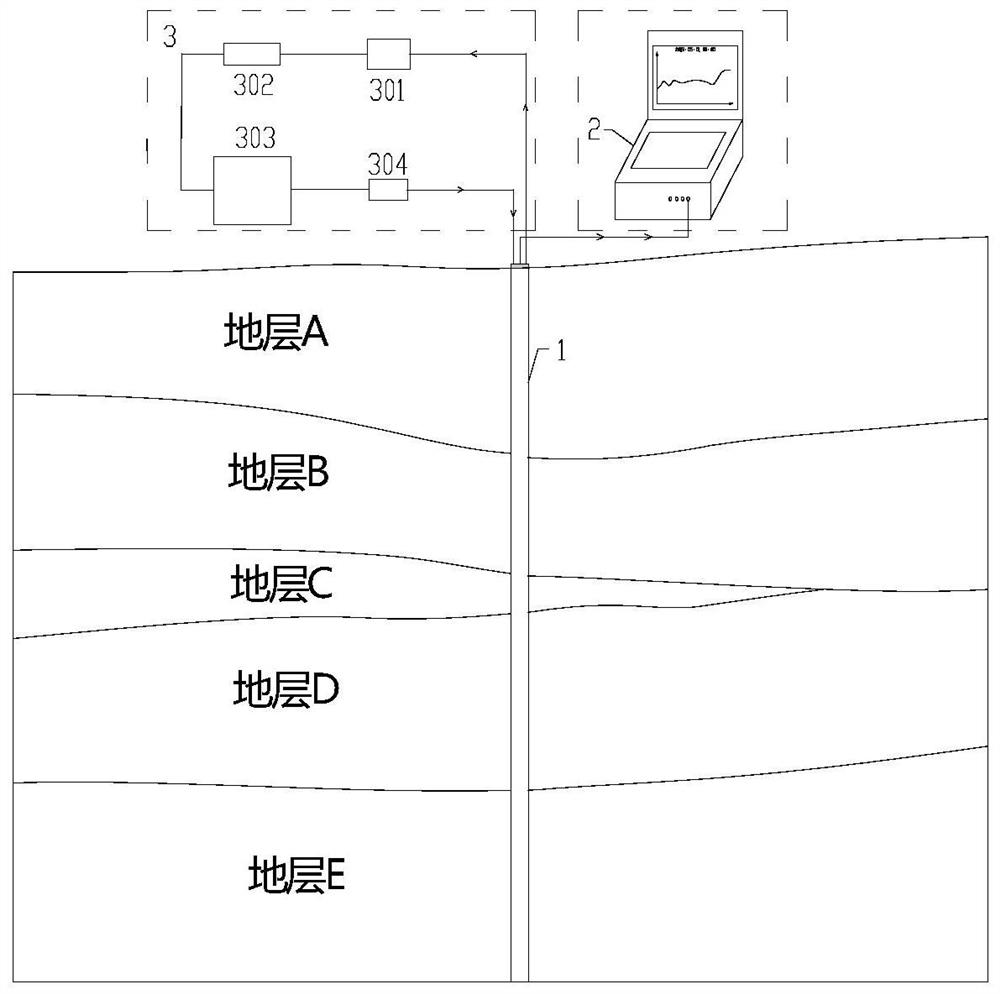
[0077] Take a specific embodiment as an example below to illustrate the specific implementation process and test effect of the present invention, and the installation of the test system is referred to figure 1 .
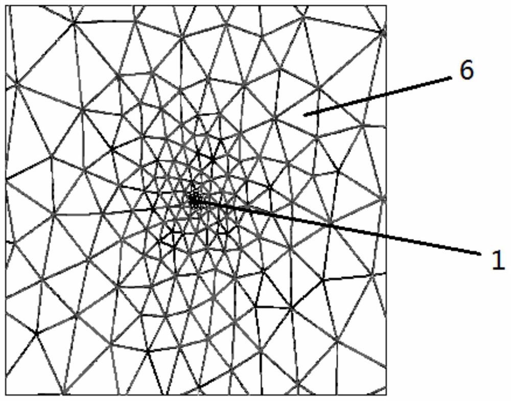
[0078] Step S1, burying the composite optical cable 1 in the soil body 6 to be tested;
[0079] The composite optical cable 1 is respectively connected with the optical signal processing control module 2 and the heating control module 3 to form an optical path and a heating circuit, and the connectivity of the optical path and the heating circuit is tested respectively.
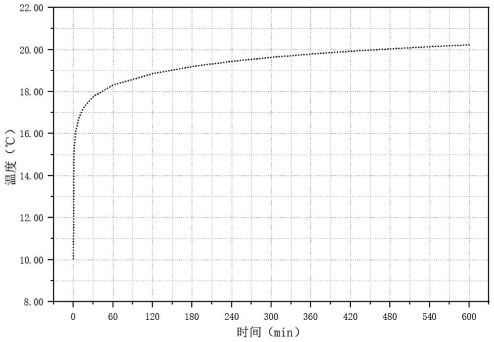
[0080] Step S20, using the optical signal processing control module to collect the initial temperature of the soil to be measured, the collection interval is 0.5min, and the collection time t1≥30min; determine the standard deviation σ of the initial temperature, if the standard deviation σ>0.5 °C, repeat the step S20; if the standard deviation σ≤0.5 °C, store the initial temperature, and execute st...
Embodiment 2
[0096] like Figure 5-6 As shown, take the vertical test embodiment in a specific borehole as an example to illustrate the specific implementation process and test effect of the present invention. The depth of drilling is 95m, and the radius of the borehole is 153mm. The borehole is backfilled with fine sand, and the coupling time is longer than 6 months.
[0097] Step S1, burying the composite optical cable 1 in the soil body 6 to be tested by drilling, the composite optical cable 1 is arranged in a U shape on the wall of the transduction tube 5, which includes a sinking section 11 and a section opposite to the sinking section. The return section 12, the interval between the sinking section and the return section is 3-5cm, and the heating power q per unit length is twice the heating power per unit length of a single composite optical cable. The inner diameter of the transducer tube is 30mm, and the outer diameter is 32mm. It is arranged in the center of the borehole in a dou...
PUM
| Property | Measurement | Unit |
|---|---|---|
| thermal conductivity | aaaaa | aaaaa |
Abstract
Description
Claims
Application Information