Long-stroke no-killing well working device of oil-water well

An operation device and long-stroke technology, applied in wellbore/well components, drilling equipment, cleaning appliances, etc., can solve the problems of difficult operation, long disassembly and assembly time, affecting the operation progress, etc., which is conducive to popularization and application and improves operation efficiency. , the effect of improving work efficiency

Inactive Publication Date: 2012-07-11
王秀忠
View PDF4 Cites 7 Cited by
  • Summary
  • Abstract
  • Description
  • Claims
  • Application Information

AI Technical Summary

Problems solved by technology

[0003] When snubbing the tubing, pluggers are often used to temporarily block the tubing. However, due to downhole tubing fouling and wax deposition, sometimes the pluggers cannot be put into the predetermined position, which affects the operation. Different devices are required for cleaning the oil pipe and lifting the oil pipe, which is troublesome to disassemble, difficult to operate, and high op

Method used


Image

  • Long-stroke no-killing well working device of oil-water well
  • Long-stroke no-killing well working device of oil-water well
  • Long-stroke no-killing well working device of oil-water well

Examples


Embodiment approach 1

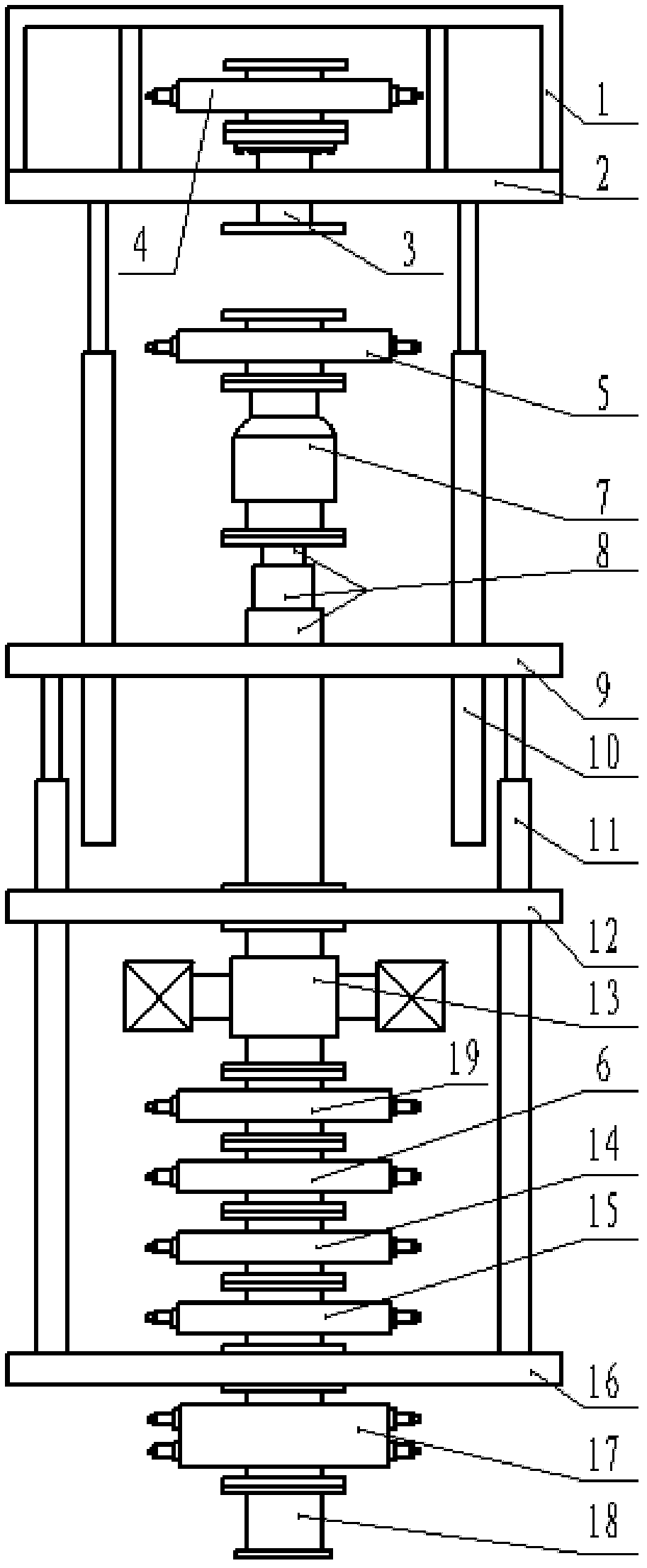
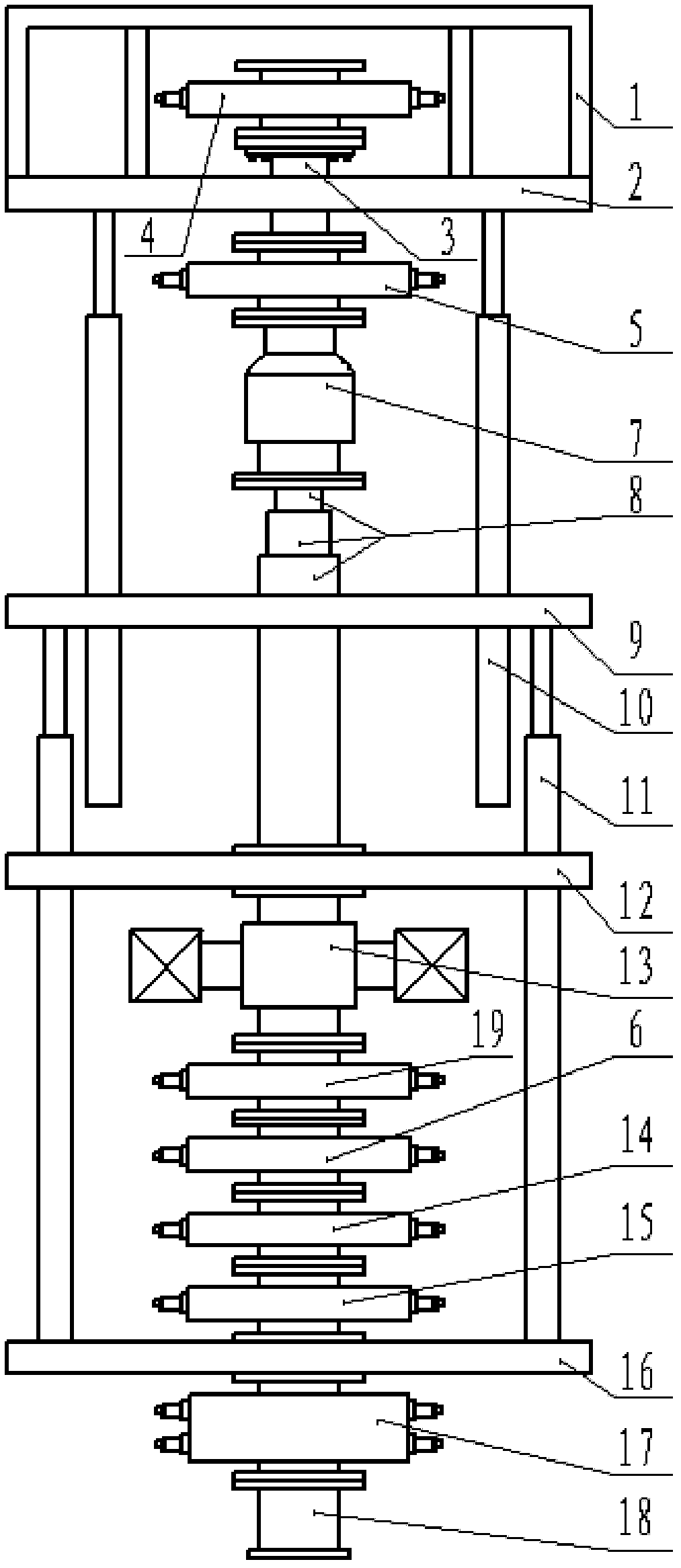
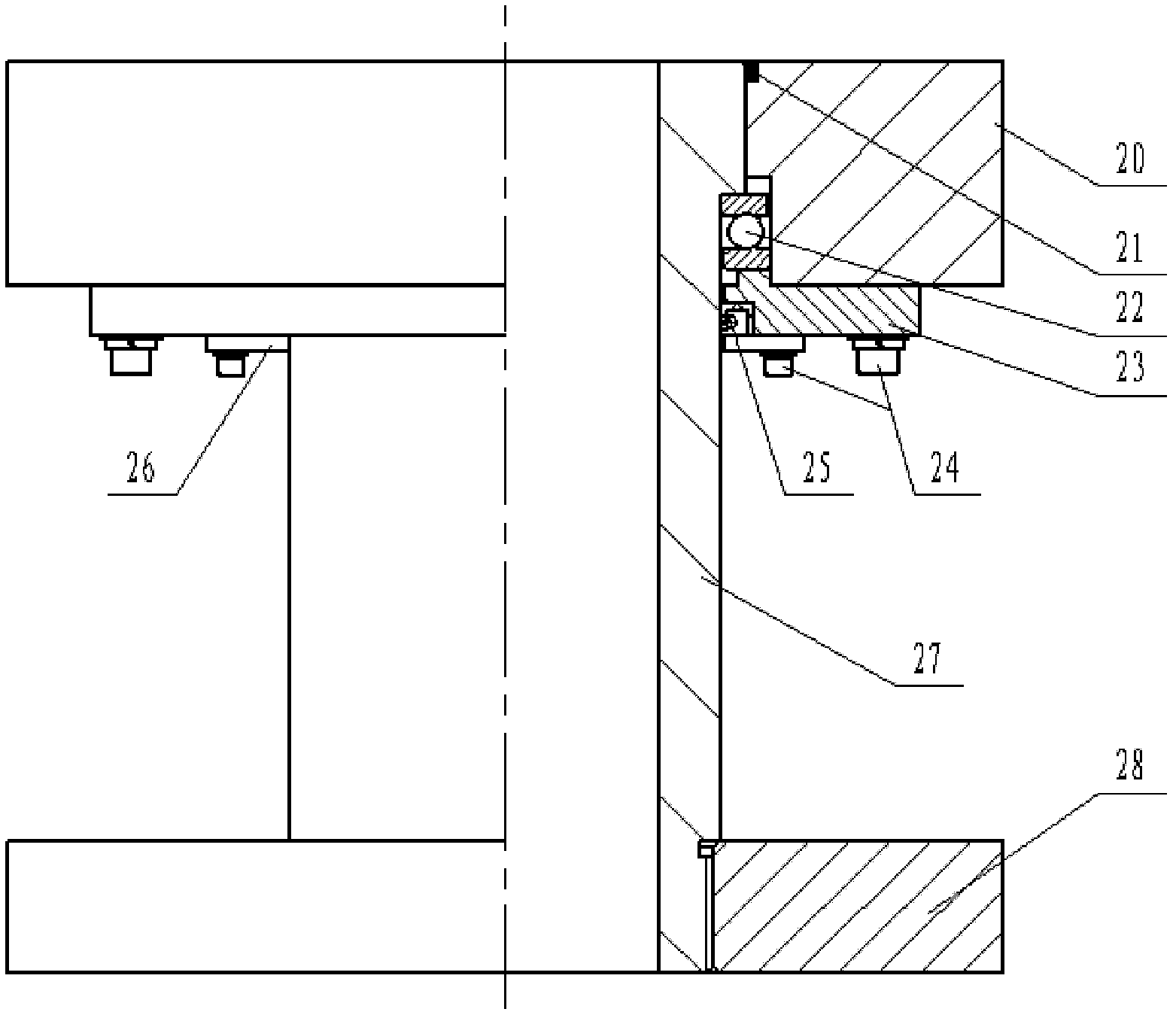
[0022] The present invention includes a guardrail 1, a working platform 2, a rotating flange 3, a moving slip 4, an upper half-enclosed blowout preventer 5, a lower half-enclosed blowout preventer 6, an annular blowout preventer 7, a telescopic cylinder 8, an intermediate platform 9, Multi-stage hydraulic cylinder 10, lifting hydraulic cylinder 11, support platform 12, wellhead cross 13, shear blowout preventer 14, fixed slips 15, lower platform 16, double ram blowout preventer 17, reducing flange 18 , Fully sealed blowout preventer 19, upper flange 20, dustproof ring 21, bearing 22, large retaining ring 23, screw 24, sealing ring 25, small retaining ring 26, sleeve 27, lower flange 28, operating rod 30 , cleaning tool 31, guardrail 1 is installed around the upper end face of working platform 2; Rotating flange 3 is made up of upper flange 20, sleeve 27, bearing 22, large retaining ring 23, small retaining ring 26, lower flange 28, upper The flange 20 is connected with the lar...

Embodiment approach 2

[0028] The lower flange 28 of the rotating flange 3 is fixedly connected with the upper end of the upper half-sealed blowout preventer 5, so that the telescopic cylinder 8 can extend or contract as the movable slip 4 moves up and down. When lifting and lowering the oil pipe, the variable diameter flange 18 at the lower end of the device is connected to the wellhead, the annular blowout preventer 7 is not working and the annular blowout preventer 7 is in the normally open state. When the tubing is pulled up, the well pressure is sealed by the fully sealed BOP 19, and the lower half-sealed BOP 6, the fixed slip 15, the shear BOP 14, and the double ram BOP 17 are all in the open state. The slips 4 and the upper half-sealed BOP 5 clamp and seal the oil pipe and send the oil pipe to the full-sealed BOP 19 through the lifting hydraulic cylinder 11 and the multi-stage hydraulic cylinder 10, and the full-sealed BOP 19 is opened, Since the movable slip 4 is fixedly connected to the rot...


PUM


Abstract

The invention belongs to the field of machinery manufacture, in particular relates to a long-stroke no-killing well working device of an oil-water well. The long-stroke no-killing well working device of the oil-water well comprises a moving slips, an annular blowout preventer, a totally-enclosed blowout preventer, an upper half-enclosed blowout preventer, a lower half-enclosed blowout preventer, a hoisting hydraulic cylinder, a wellhead four-way, a cutting blowout preventer, a fixed slips, a double-disc blowout preventer, a reducing flange, an operating rod and a cleaning tool. The long-stroke no-killing well working device is characterized in that the device also comprises a flexible rod, a multistage hydraulic cylinder and a rotation flange. The stroke of operation is improved by using the multistage hydraulic cylinder and the flexible cylinder, and the moving slips can be rotatably moved by using the rotation flange to drive the operating rod and the cleaning tool to clear the fouling of an inner wall of the oil pipe in a rotating way. The device of the invention also can press a lower oil pipe under the condition of no-injection of the oil pipe. The device is convenient to operate, greatly improves the working efficiency and is favorable for generalization and application.

Description

technical field [0001] The invention belongs to the field of mechanical manufacturing, in particular to a long-stroke snubbing operation device for oil and water wells. Background technique [0002] At present, many oil fields adopt snubbing operation. Snubbing operation is an operation mode that realizes no pressure relief and no overflow in a pressurized environment. Compared with the traditional well killing operation method, it is safer and more efficient. Environmental friendly. Because the snubbing operation device has good sealing and blowout prevention functions, it can effectively reduce the stoppage time of water well injection, increase the water injection rate, avoid reservoir damage caused by water spit, reduce invalid water injection, save water injection costs, and eliminate environmental pollution. It can also effectively avoid the phenomenon of production shutdown and liquid production drop caused by well killing, and more importantly, it can avoid reservo...

Claims


Application Information

Patent Timeline
IPC IPC(8): E21B33/03E21B37/00E21B19/00
Inventor 刘延俊宋志强王秀忠李超孙兴旺彭建军郝宁程波
Owner 王秀忠
Why Eureka
Try Eureka