Bi-directional actuator utilizing both attractive and repulsive electrostatic forces

a bi-directional actuator and electrostatic force technology, applied in piezoelectric/electrostrictive devices, device details, electrostatic generators/motors, etc., can solve the problems of limited application of attractive electrostatic actuators of conventional parallel plates, increased fabrication complexity, and reduced space utilization efficiency, so as to achieve the effect of easy integration into mems devices

Inactive Publication Date: 2010-04-27
HE +1
View PDF14 Cites 7 Cited by
  • Summary
  • Abstract
  • Description
  • Claims
  • Application Information

AI Technical Summary

Benefits of technology

[0020]In particular, the invention provides a repulsive electrostatic actuator by arranging electrodes to generate, when a repulsive force is desired, an asymmetric field around the moving electrodes leading to a net repulsive force. Moreover, the invention provides a bi-directional electrostatic actuator which combines both attractive and repulsive forces to drive the moving electrodes toward and away from the fixed electrodes, thereby increasing the total stroke of conventional parallel plate attractive electrostatic actuators. The invention relies on a special arrangement of electrodes whereby the moving electrodes are subject to either an attractive or a repulsive force depending on the voltage applied. In general, the invention provides a bi-directional electrostatic actuator with a simple structure, e.g., only two conductive layers are needed such that it can be easily incorporated with MEMS devices without adding extra fabrication complexity and is compatible with standard surface micromachining technology.
[0022]In accordance with a particular embodiment of the invention, the adjacent fixed electrodes are elevated through support posts to be in the same plane as the moving electrodes when no voltage is applied. When the moving electrodes and the elevated adjacent fixed electrodes are supplied with a voltage V1, and the aligned fixed electrodes are supplied with a voltage V2, where V1≠[ ]V2, an attractive force is generated to move the moving electrodes towards the aligned fixed electrodes. When the aligned electrodes in both arrays are supplied with a voltage V1, and the elevated unaligned adjacent fixed electrodes are supplied with V2, a repulsive force is generated to move the moving electrodes away from the fixed electrodes. Preferably, the moving electrodes are only subject to a single voltage, thereby eliminating any requirement for additional insulating layers on the moveable element or any wiring complexity. Preferably, the moveable element has only two structural layers.
[0023]Advantageously, the bi-directional large-stroke electrostatic actuator of the present invention can be implemented with standard surface micromachining techniques and easily incorporated into MEMS devices such as optical switches, RF switches, tunable capacitors, micromirrors, micro gyroscopes, and the like.

Problems solved by technology

The application of conventional parallel plate attractive electrostatic actuators is limited by the “pull-in” effect: when the displacement of the moving electrode exceeds ⅓ of the initial gap distance, the linear restoring force from the flexures cannot counteract the rapidly increasing nonlinear electrostatic attractive force between the fixed and moving electrodes, and as such the moving electrode sticks to the fixed electrode.
By using the elevation mechanism a larger stroke is achieved at the price of increased fabrication complexity, lower space usage efficiency, lower production yield and higher driving voltage.
Moreover, the special control circuit increases the cost of the chip.
All the attempts mentioned above to increase the stroke of the conventional parallel-plate attractive electrostatic actuators, are either not adequate to achieve a stroke large enough for many applications or are not compatible with standard surface micromachining technology and thus are difficult to implement in a batch-production process.
This design has a serious drawback which limits it from being widely used as a bi-directional large stroke electrostatic actuator in MEMS devices, namely, the moving electrodes require electric potentials with opposite polarities thereby a movable insulation layer, such as silicon nitride or silicon oxide, has to be added to physically constrain and electrically insulate all the moving electrodes.
These requirements complicate the fabrication process, lead to a deterioration of the performance of the component, and add wiring complexity.
Moreover, no moving insulation layer is available in many commercial MEMS fabrication processes such as MUMPS (Multi User MEMS Processes), SUMMIT (Sandia Ultra planar Multilevel MEMS Technology), and so on.

Method used


Image

  • Bi-directional actuator utilizing both attractive and repulsive electrostatic forces
  • Bi-directional actuator utilizing both attractive and repulsive electrostatic forces
  • Bi-directional actuator utilizing both attractive and repulsive electrostatic forces

Examples


example 1

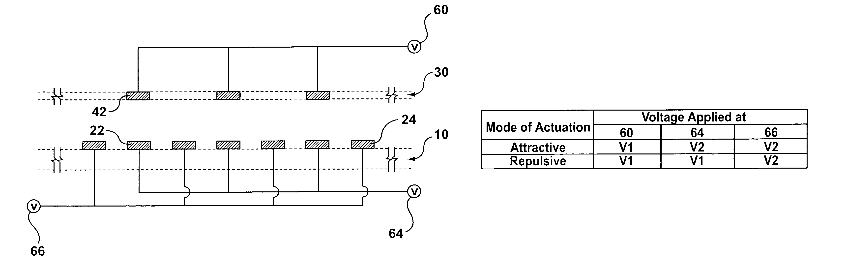
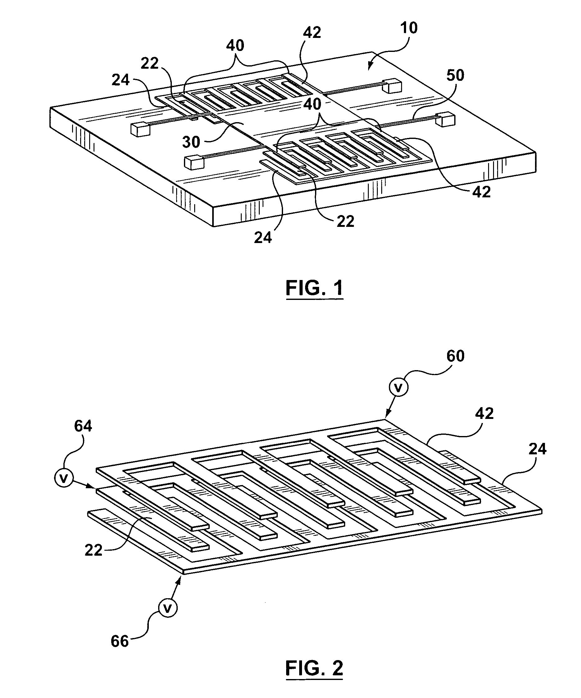
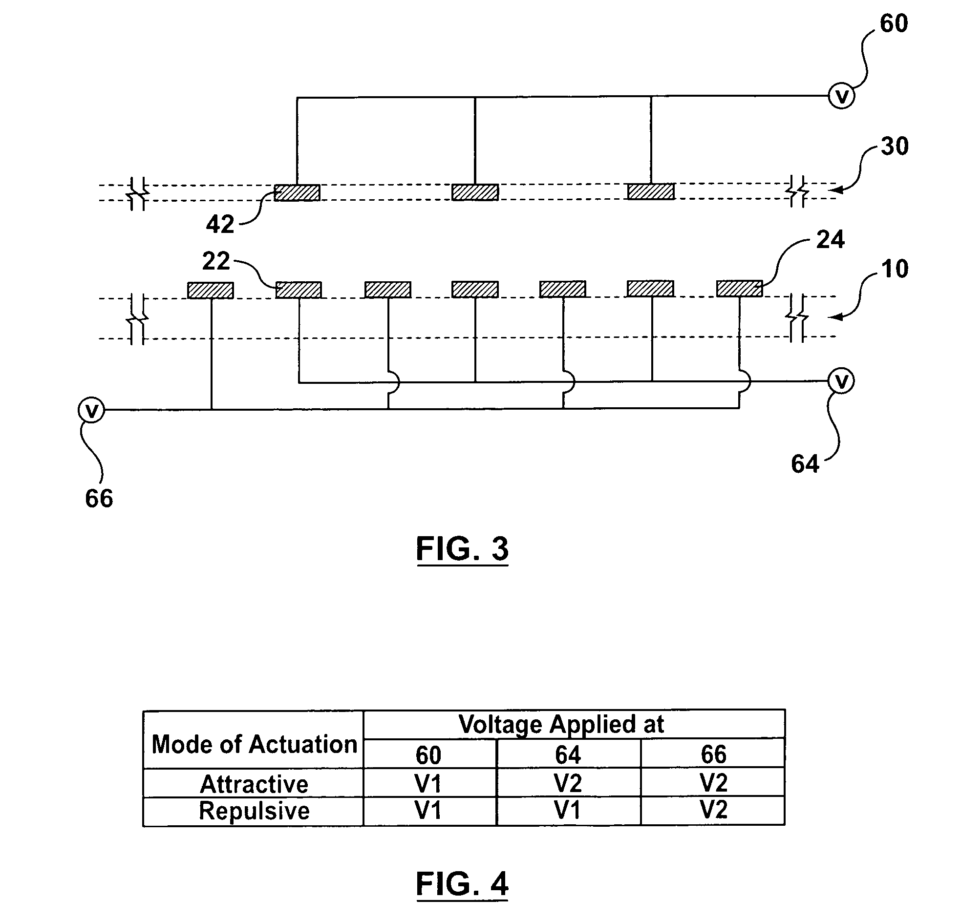
[0077]The bi-directional electrostatic actuator of this example is schematically shown as FIG. 1. FIG. 2 shows part of the electrodes of the actuator shown in FIG. 1—The section view of electrodes is shown as FIG. 3. The width of the moving electrodes 42 and that of the fixed electrodes 22, 24 are not necessarily equal. Normally, the moving electrodes 42 are slightly narrower than the aligned fixed electrodes 22 in order to accommodate for any undesired displacement during operation and for misalignments due to fabrication in the plane parallel to the plane of the electrodes. The minimum number of moving electrodes 42 is 1 and the minimum number of fixed electrodes 22, 24 is 3. There is no limitation on the maximum number of moving and fixed electrodes.

[0078]All the electrodes are made of electrically conductive material. As shown in FIG. 3, all moving electrodes 42 in the actuator are electrically connected to a voltage source 60. Aligned fixed electrodes 22 on the base 10 are elec...

example 2

[0091]The bi-directional electrostatic actuator of this example is schematically shown in FIG. 15. FIG. 16 shows part of the electrodes of the actuator shown in FIG. 15. A section view of the electrodes is shown in FIG. 17(a).

[0092]As shown in FIG. 15, the moving electrodes 42 have a set of aligned fixed electrodes 22 on the base 10. The unaligned fixed adjacent electrodes 24 are elevated to the same plane as the moving electrodes 42 by supporting posts 52.

[0093]As shown in FIGS. 16 and 17 (a), all moving electrodes 42 in the actuator are electrically connected to a voltage source 60. Aligned fixed electrodes 22 on the base 10 are electrically connected to voltage source 64. Unaligned fixed adjacent electrodes 24 are connected and subject to voltage source 66.

[0094]The bi-directional electrostatic actuator of this example can work in two modes, i.e., the attractive mode and the repulsive mode. When working in the attractive mode, the electrodes are subject to potentials in the manne...


PUM


Abstract

An electrostatic actuator comprising: first and second comb arrays of electrodes arranged on a base, the electrodes of the first and second comb arrays being interleaved; a third comb array of electrodes spring mounted over the first and second comb arrays, the electrodes of the third comb array being essentially aligned with the electrodes of the second comb array; means for applying a first voltage to the third comb array and a second voltage to the first and second comb arrays to generate an attractive force acting on the third comb array to move the third comb array toward the second comb array; and, means for applying the first voltage to the second and third comb arrays and the second voltage to the first comb array to generate a repulsive force acting on the third comb array to move the third comb array away from the second comb array.

Description

FIELD OF THE INVENTION[0001]The invention relates to the field of electrostatic actuators, and more particularly, to micro electrostatic actuators to be used in applications including optical MEMS devices, RF MEMS devices, and MEMS memory.BACKGROUND OF THE INVENTION[0002]Microelectromechanical systems (MEMS) are the integration of mechanical elements and electronics on the same chip using microfabrication technology similar to the IC process to realize high performance and low cost functional devices such as micro sensors and micro actuators.[0003]MEMS is becoming an enabling technology in many fields as it enables the construction of devices or systems characterized by high performance, small size, small weight and low cost. Typical MEMS applications include: inertial measurement units such as micro accelerometers and micro gyroscopes; optical MEMS such as digital light processing (DLP) systems, micro optical switches and micromirrors for adaptive optics; and, RF MEMS devices such ...

Claims


Application Information

Patent Timeline
Patent Type & Authority Patents(United States)
IPC IPC(8): H02N1/00G02B26/08
CPCH02N1/006
Inventor HEBEN MRAD, RIDHA
Owner HE
Why Eureka
Try Eureka