
Apparatus and method for repairing liquid crystal display device

a liquid crystal display and apparatus technology, applied in non-linear optics, instruments, optics, etc., can solve the problems of small viewing angle, inability to repair by laser rework, and small aperture ratio, so as to reduce the defect ratio of the bright point, improve the yield, and minimize the defect ratio

Active Publication Date: 2009-12-22
LG DISPLAY CO LTD
View PDF3 Cites 12 Cited by
  • Summary
  • Abstract
  • Description
  • Claims
  • Application Information

AI Technical Summary

Benefits of technology

The present invention is about an apparatus and method for repairing a liquid crystal display panel. The invention improves yield by darkening defect points in the panel to minimize the number of defects. The apparatus includes a repair film formed on a substrate and a laser irradiating device to darken the defect area. The repair film can be a transparent organic film or a black matrix. The invention can be used to repair various defects in the panel such as bright points, dark points, and common electrode defects. The method includes sensing the defect area, irradiating a laser to the defect area, and adjusting the laser's irradiation area and focus distance using a focus controller. The invention provides a more efficient and effective way to repair liquid crystal display panels.

Problems solved by technology

The TN mode has an advantage in that its aperture ratio is big, but a disadvantage in that its viewing angle is small.
The IPS mode has an advantage in that its viewing angle is big, but a disadvantage in that its aperture ratio is small.
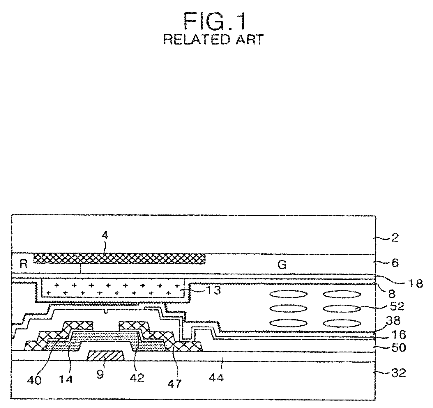
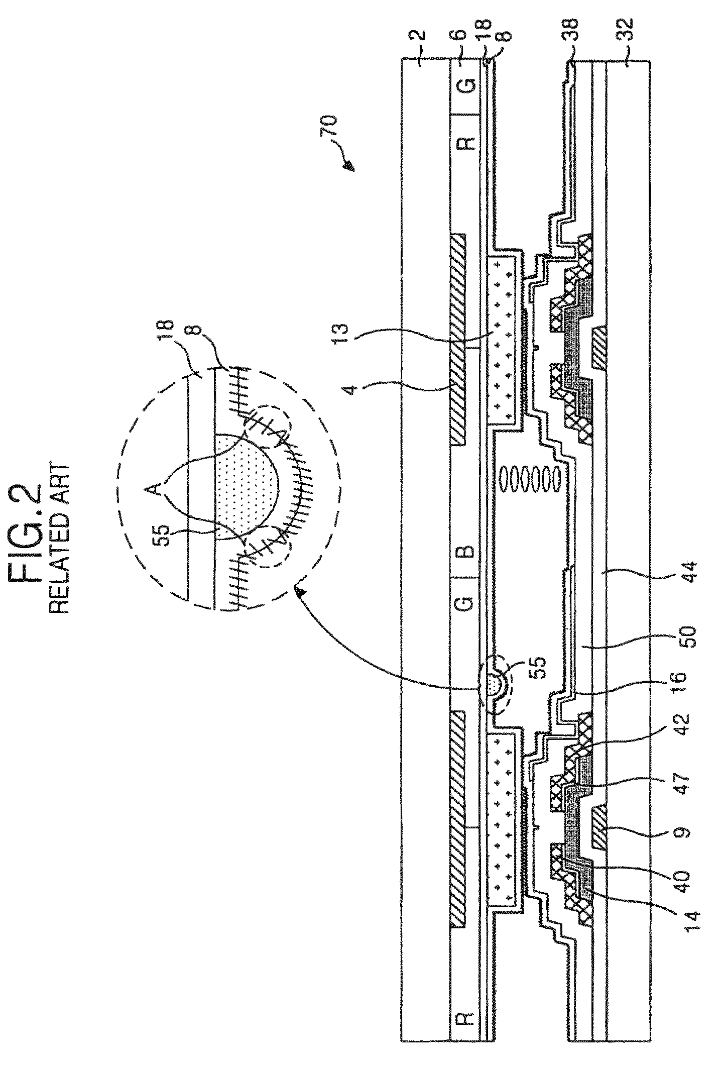
However, if a particle is soundly settled between the thin films of both the upper array substrate and the lower array substrate, it becomes impossible to do the repair by rework or laser.
In this example the alignment film corresponding to the particle 55 is not uniformly rubbed in a rubbing process, thereby generating a non-uniform alignment area A. Further, a portion of the color filter is separated by a defect on the process upon forming the color filter.
Such particles 55 intermixed between layers may occur frequently causing various problems in the LCD panel.
For example, the non-uniform alignment area A causes light leakage in the liquid crystal display panel, and such light leakage interferes with light transmittance of the liquid crystal material.

Method used


Image

  • Apparatus and method for repairing liquid crystal display device
  • Apparatus and method for repairing liquid crystal display device
  • Apparatus and method for repairing liquid crystal display device

Examples


first embodiment

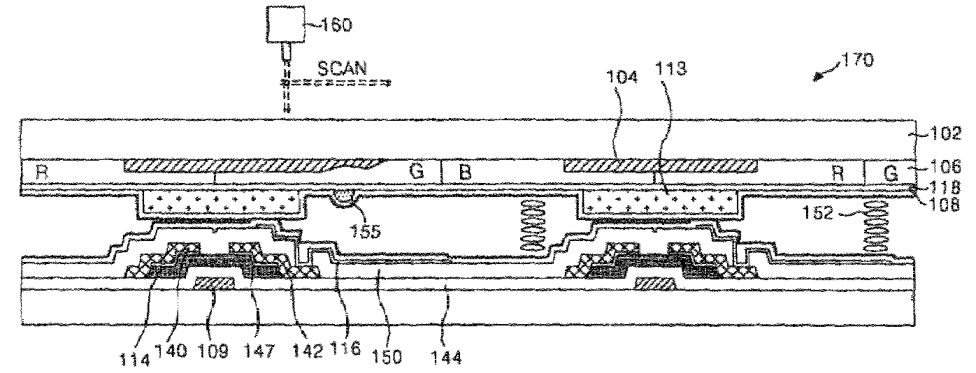
[0067]FIG. 4 is a sectional view illustrating an apparatus for repairing a liquid crystal display panel according to the present invention.

[0068]Referring to FIG. 4, an apparatus for repairing a liquid crystal display panel according to the first embodiment of the present invention includes a liquid crystal display panel 170 having a repair film (hereinafter, referred to as “transparent organic film”) 120. The transparent organic film 120 may be used to darken an area where there is a bright point on the liquid crystal display panel 170 caused by an alignment defect resulting from a particle 155 intermixed in the liquid crystal display panel 170. The apparatus further includes a laser irradiating device 160 to irradiate a laser to the transparent organic film 120 to darken the transparent organic film 120 in an area corresponding to a bright point.

[0069]The liquid crystal display panel 170 includes an upper array substrate (or a color filter array substrate) having a black matrix 10...

second embodiment

[0091]FIG. 7 is a sectional view illustrating an apparatus for repairing a liquid crystal display panel according to the present invention.

[0092]Referring to FIG. 7, an apparatus for repairing a liquid crystal display panel according to the second embodiment of the present invention includes a laser irradiating device 260, which irradiates a laser to a black matrix 204 of an area near to the area where a bright point is generated to darken the area where a particle 255 is intermixed.

[0093]The liquid crystal display panel 270 includes an upper array substrate (or a color filter array substrate) having a black matrix 204, a color filter 206, a common electrode 218, a pattern spacer 213, and an upper alignment film 208 that are sequentially formed on an upper substrate 202; a lower array substrate having a thin film transistor (hereinafter, referred to as “TFT”), a pixel electrode 216 and a lower alignment film 238 that are formed on a lower substrate 232; and a liquid crystal material...

third embodiment

[0111]FIG. 10 is a sectional view illustrating an apparatus for repairing a liquid crystal display panel according to the present invention.

[0112]Referring to FIG. 10, an apparatus for repairing a liquid crystal display panel according to the third embodiment of the present invention includes a laser irradiating device 360, which irradiates a laser to a pattern spacer 313 of an area near to the area where a bright point is generated to darken the area where a particle 355 is intermixed.

[0113]The liquid crystal display panel 370 includes an upper array substrate (or a color filter array substrate) having a black matrix 304, a color filter 306, a common electrode 318, a pattern spacer 313, and an upper alignment film 308 which are sequentially formed on an upper substrate 302; a lower array substrate having a thin film transistor (hereinafter, referred to as “TFT”), a pixel electrode 316 and a lower alignment film 338 which are formed on a lower substrate 332; and a liquid crystal mat...


PUM

PropertyMeasurementUnit
wavelengthaaaaaaaaaa

Abstract

The present invention relates to an apparatus and method for repairing a liquid crystal display panel, which is capable of improving a yield thereof by darkening a bright point to minimize a defect ratio thereof. An apparatus for repairing a liquid crystal display panel according to the present invention includes: a liquid crystal display panel including a repair film formed on any one of a first substrate and a second substrate, which are facing to each other with a liquid crystal layer therebetween; and a laser irradiating device to irradiate a laser to the repair film to darken a specific area of the repair film, which is corresponded to an area where a bright point appears in the liquid crystal display panel.

Description

[0001]This application claims the benefit of Korean Patent Application Nos. P2004-105889, P2004-105891, and P2004-105892, filed on Dec. 14, 2004, which is hereby incorporated by reference for all purposes as if fully set forth herein.BACKGROUND OF THE INVENTION[0002]1. Field of the Invention[0003]The present invention relates to an apparatus and method for repairing a liquid crystal display panel, and more particularly, to an apparatus and method for repairing a liquid crystal display panel, which is capable of improving a yield thereof by darkening a bright point to minimize a defect ratio thereof.[0004]2. Discussion of the Related Art[0005]Generally, a liquid crystal display (LCD) device controls the light transmittance of a liquid crystal material in accordance with a video signal to display a picture. For this, the liquid crystal display device includes a liquid crystal display panel in which liquid crystal cells are arranged in a matrix configuration, and a drive circuit to dri...

Claims


Application Information

Patent Timeline
Patent Type & Authority Patents(United States)
IPC IPC(8): G02F1/13
CPCG02F1/136259
Inventor YOO, SOON SUNGKWON, OH NAMCHO, HEUNG LYULNAM, SEUNG HEE
Owner LG DISPLAY CO LTD
Learn More