
Compression encoder, compression-encoding method, recorder, and recording method

a compression encoder and encoder technology, applied in the field of compression encoders, compression encoders, compression encoders, recorders, etc., can solve the problems of interpolation processing, prolonged period, resolution hence deterioration, etc., and achieve the effect of reducing the number of decoders and restricting the resolution

Inactive Publication Date: 2009-12-22
SONY CORP
View PDF10 Cites 2 Cited by
  • Summary
  • Abstract
  • Description
  • Claims
  • Application Information

AI Technical Summary

Benefits of technology

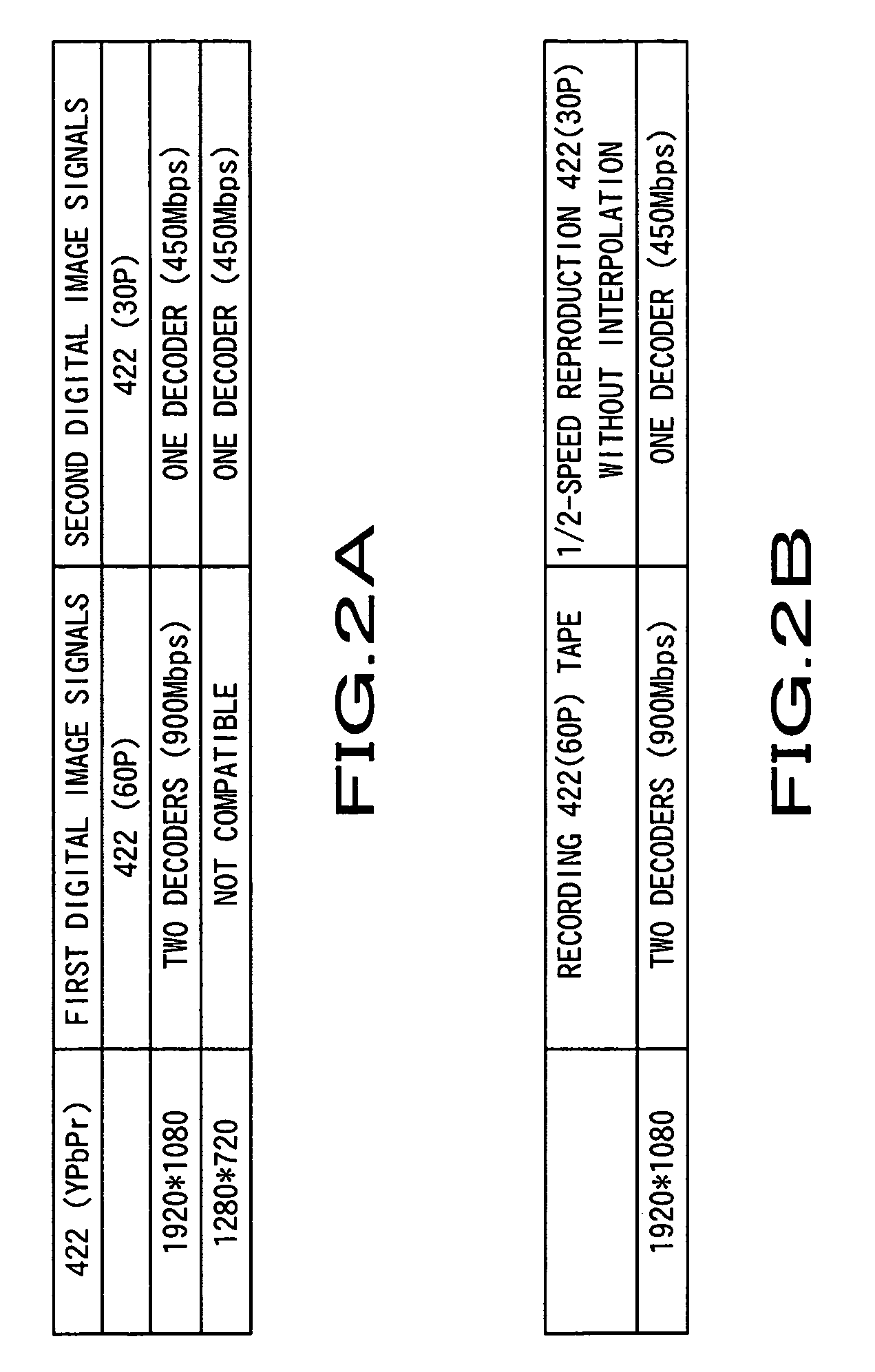
[0011]An object of the present invention is to provide a compression encoder, a compression-encoding method, a recorder, and a recording method by which the number of decoders necessary for ½-speed reproduction of the first digital signal can be reduced by improving a method of shuffling the first digital image signal, and deterioration of resolution can be restricted without necessitating an interpolation processing.
[0023]As a result of this, the compression encoder and compression-encoding method are capable of compression-encoding data so that deterioration in resolution can be restricted when the first digital image signals recorded on a recording medium is subjected to ½-speed reproduction and the number of decoders can be reduced.
[0025]As a result of this, the recorder and recording method are capable of compression-encoding and recording data so that deterioration in resolution can be restricted when the first digital image signals recorded on a recording medium is subjected to ½-speed reproduction and the number of decoders can be reduced.

Problems solved by technology

In this case, if the frame rate of 60 frames / second is subjected to ½-speed reproduction as described above, an interpolation processing is required and the resolution hence deteriorates.
There has been a problem that the development period is prolonged in addition to increase in development costs of the whole signal processor.
However, shuffling methods for rearranging macro blocks in accordance with formats are different between both of the formats.
Therefore, two decoders are finally required for reproduction, resulting in a problem that labor saving in developments and speed-up of reproduction processings cannot progress.
Note that the same problem occurs in other encoding systems such as a 4:4:4 format and the like.

Method used


Image

  • Compression encoder, compression-encoding method, recorder, and recording method
  • Compression encoder, compression-encoding method, recorder, and recording method
  • Compression encoder, compression-encoding method, recorder, and recording method

Examples


Embodiment Construction

[0048]Hereinafter, embodiments of the present invention will be described in details with reference to the drawings.

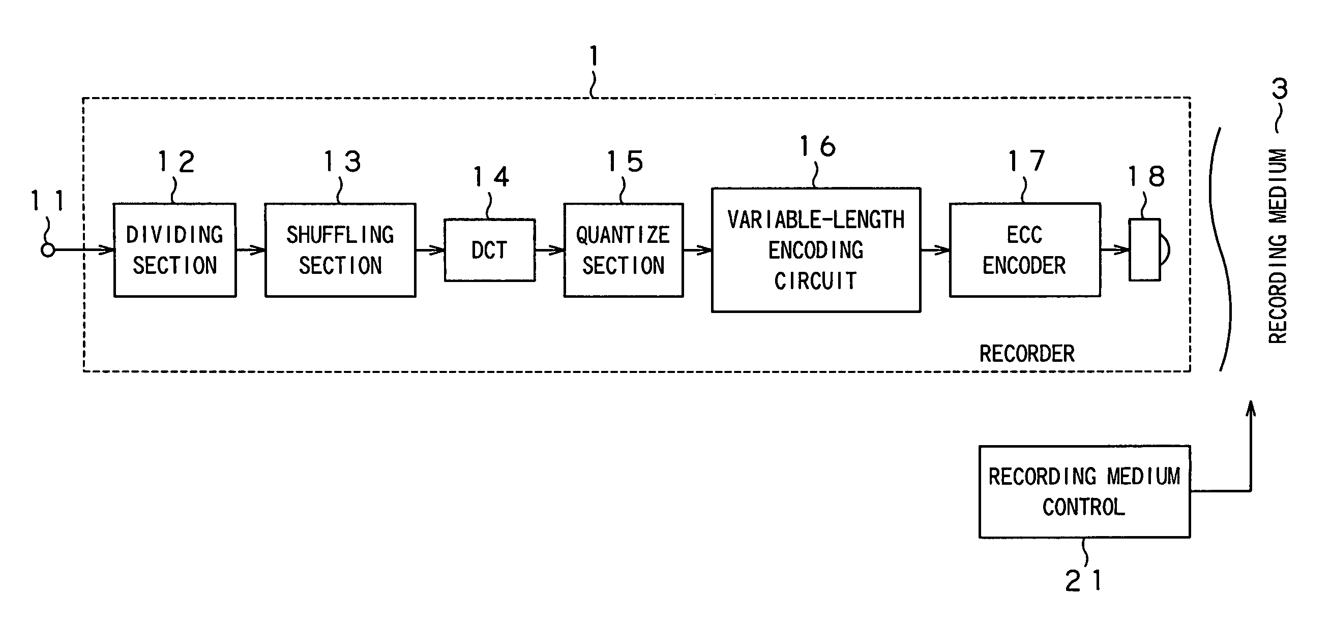
[0049]The present invention is applied to a recorder 1, for example, as shown in FIG. 1. The recorder 1 shuffles inputted digital image signals in units of micro blocks and subjects the signals to DCT (Discrete Cosine Transform) conversion. Besides, the recorder 1 then quantizes the signals. Irreversible image compression is thus achieved, and the compressed signals are recorded onto a recording medium 3.

[0050]The recorder 1 has an input terminal 11, a dividing section 12, a shuffling section 13, DCT (Discrete Cosine Transform) circuit 14, a quantize circuit 15, a variable-length encoding circuit 16, an ECC encoder 17, a recording section 18, and a recording medium control section 21. The input terminal 11 is inputted with luminance signals Y, color difference signals Cb and Cr, and digital image signals of R, G, and B. The dividing section 12 divides the inputted imag...


PUM


Abstract

The number of decoders necessary for ½-speed reproduction is reduced and deterioration in resolution is restricted without necessitating an interpolation processing. First digital image signals and second digital image signals having a different frame rate from that of the first digital image signals are compressed on the basis of one same encoding system. Based on a method of rearranging macro blocks of the second digital image signals, the macro blocks of the first digital image signals are rearranged, so that the respective digital image signals compression-encoded and outputted can have macro block layouts equivalent to each other.

Description

BACKGROUND OF THE INVENTION[0001]1. Field of the Invention[0002]The present invention relates to a compression encoder and a compression-encoding method by which first and second digital image signals having frame rates different from each other are compressed on the basis of an equal encoding method, and a recorder and a recording method by which digital image signals thus compressed are recorded onto a recording medium.[0003]2. Description of the Related Art[0004]In the past, there have been proposals for a VTR (Video Tape Recorder) capable of reproducing video signals recorded on recording media according to various formats and of further converting the signals into different formats (ref. Jpn. Pat. Appln. Laid-Open Publication No. 2-171090). In this conventional VTR, the operation state can be changed automatically based on the system of video signals to be reproduced and that of video signals to be set. Determination of the recorded television system can be made by measuring th...

Claims


Application Information

Patent Timeline
Patent Type & Authority Patents(United States)
IPC IPC(8): H04N7/12H04N11/02H04N5/92H03M7/30H04N5/783H04N9/804H04N19/00H04N19/423H04N19/625H04N19/65H04N19/85H04N19/88H04N19/91
CPCH04N9/8047H04N19/88H04N19/60H04N19/176H04N5/783
Inventor ISHII, MIKIOHIGUCHI, HIROSHITSUSHIMA, KATSUHIKO
Owner SONY CORP
Learn More