Flight control indicator displaying the aircraft's thrust information

a technology of thrust information and flight control, which is applied in the direction of simultaneous indication of multiple variables, navigation instruments, instruments, etc., can solve the problems of affecting the safety of passengers, and not providing sufficient information to the pilot of the aircra

Inactive Publication Date: 2009-12-22
AIRBUS OPERATIONS (SAS)
View PDF6 Cites 8 Cited by
  • Summary
  • Abstract
  • Description
  • Claims
  • Application Information

AI Technical Summary

Benefits of technology

[0011]An object of the present invention is to remedy these drawbacks. It relates to a flight control indicator for an aircraft, making it possible to provide a pilot of the aircraft with valuable aid in monitoring the thrust.
[0019]The presentation of this item of information regarding actual thrust provides valuable aid in the monitoring of the behavior of the aircraft, in particular when it is flown automatically with the aid of an automatic thrust control system, as indicated previously. This presentation of an item of information regarding actual thrust is also beneficial when a pilot flies the aircraft while looking through said head-up display, and while controlling the thrust manually. Consequently, the flight control indicator in accordance with the invention provides definite comfort to the flight control and increases the safety of the flight.

Problems solved by technology

When this limit value is reached, the speed begins to drop, and this may of course lead to a very dangerous situation, especially when the speed of the aircraft on dropping approaches the stalling speed.
Consequently, the pilot of the aircraft is not furnished with sufficient information regarding in particular the thrust engendered, in such a situation which is liable to be very dangerous, as indicated hereinabove.

Method used


Image

  • Flight control indicator displaying the aircraft's thrust information
  • Flight control indicator displaying the aircraft's thrust information
  • Flight control indicator displaying the aircraft's thrust information

Examples


first embodiment

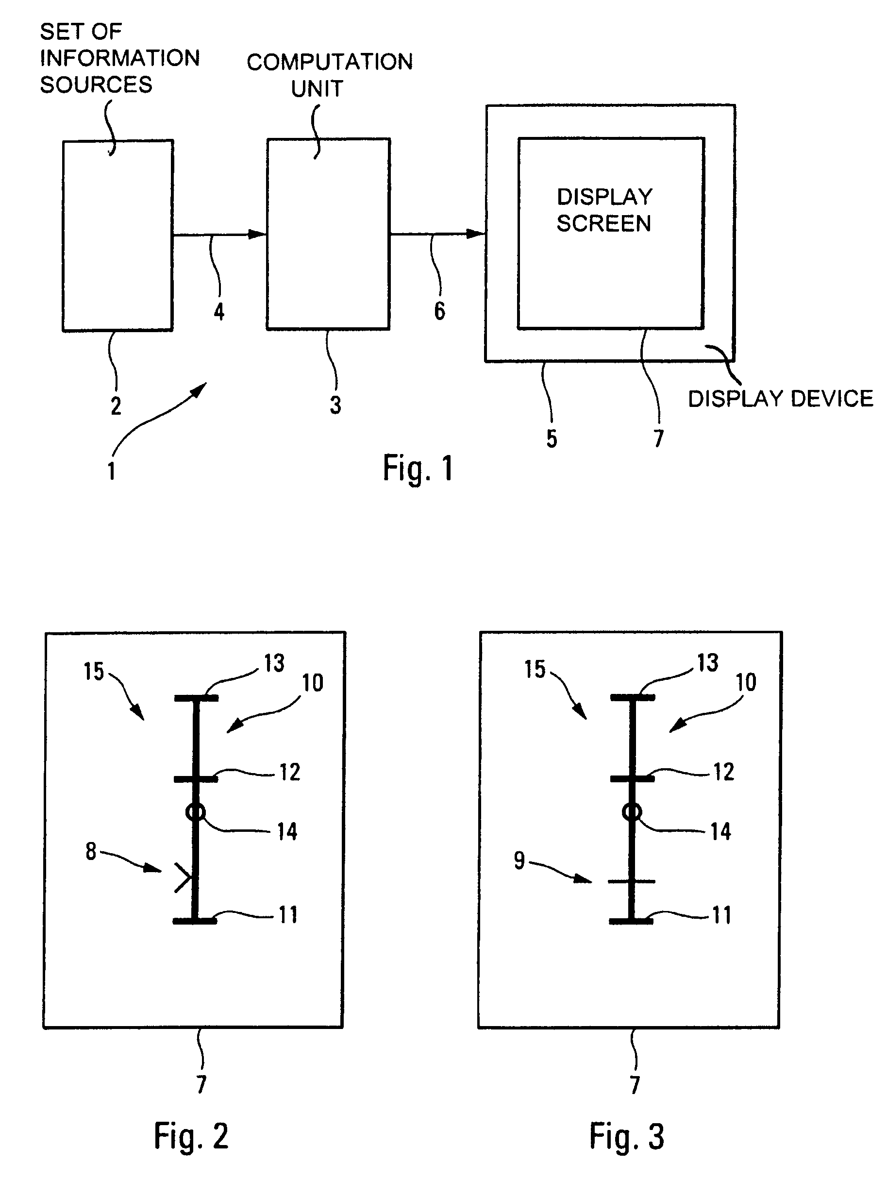
[0072]In a first embodiment represented in FIGS. 2 and 3, said computation unit 3 determines, as item of information regarding actual thrust, the mean current thrust of all the m engines M1, M2, M3 and M4 of the aircraft (m being an integer greater than 1), and said display device 5 presents, on said display screen 7, a single means of indication 8, 9 which indicates said mean current thrust (and hence a single indicator set 15).

second embodiment

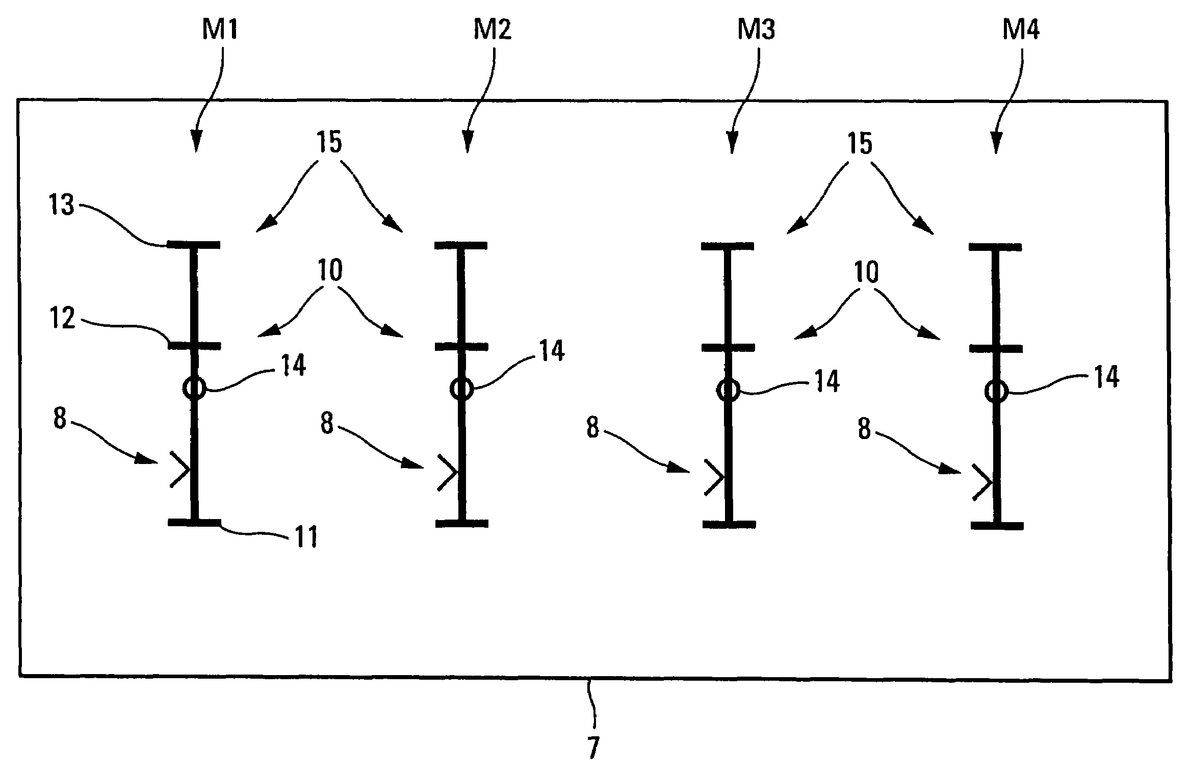
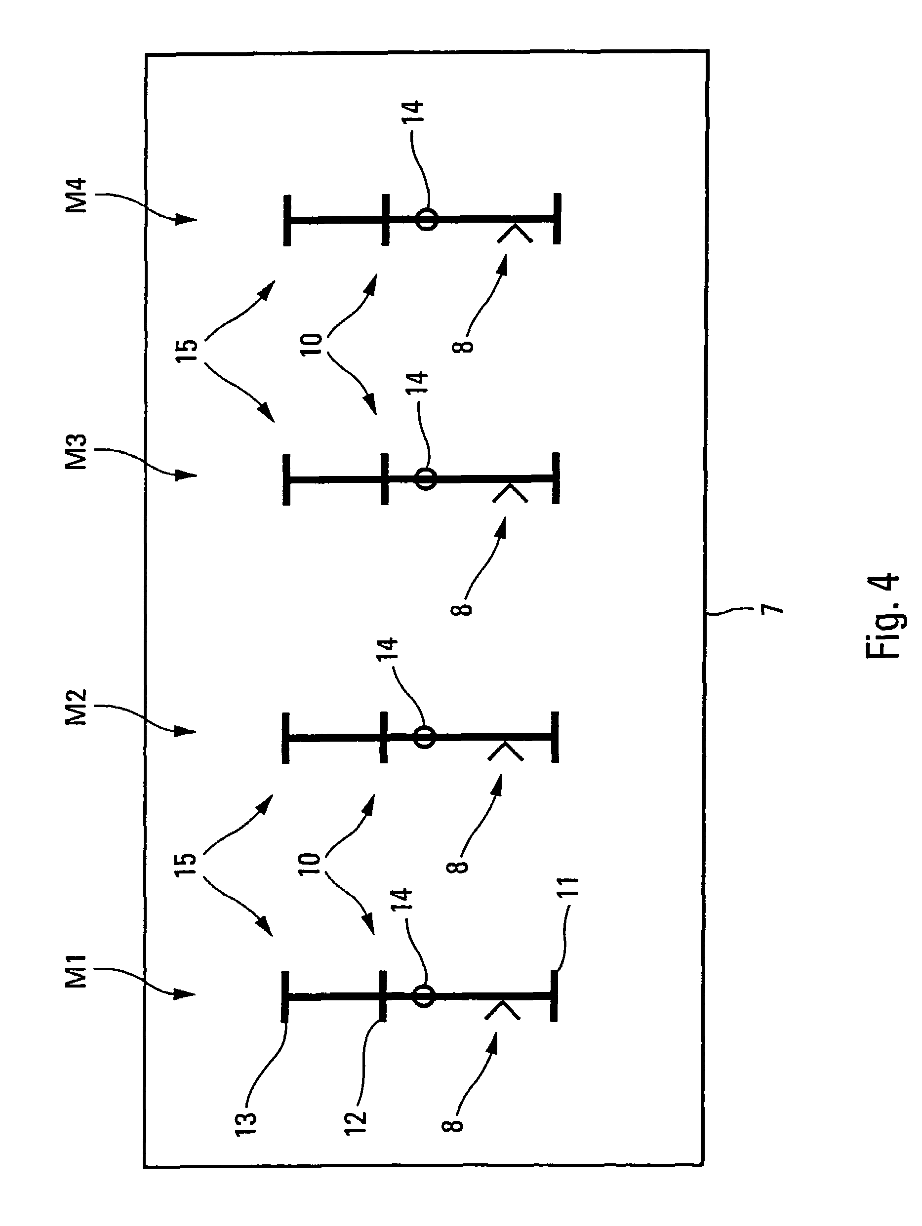
[0073]Furthermore, in a second embodiment represented in FIG. 4, said computation unit 3 determines n items of information regarding actual thrust, corresponding respectively to the current thrusts of each of the n engines M1, M2, M3 and M4 of the aircraft, n being an integer (which is equal to 4 in the example of FIG. 4). The display device 5 in this case presents, on the display screen 7, side by side, n different indicator sets 15 associated respectively with said n engines M1, M2, M3 and M4 of the aircraft. Each of said indictor sets 15 indicates information relating to the thrust of the corresponding engine M1, M2, M3 and M4.

[0074]This second embodiment makes it possible, as the case may be, to highlight a fault with one of said engines M1, M2, M3 and M4 and thus allows the pilot to monitor the response of the other engines (not defective) when the automatic thrust control system is activated.


PUM


Abstract

A flight control indicator for an aircraft has a set of information sources, a computation unit which determines, on the basis of information emanating from the set of information sources, an item of information regarding actual thrust of an engine of the aircraft, and a display device which is a head-up display device and which presents, on a display screen, an indication of the item of information regarding actual thrust. The item of information regarding actual thrust is associated with a thrust scale and both are presented superimposed on the environment prevailing in front of the aircraft.

Description

FIELD OF THE INVENTION[0001]The present invention relates to a flight control indicator for an aircraft.BACKGROUND OF THE RELATED ART[0002]Such a flight control indicator is more specifically adapted to an airplane, in particular a military transport airplane, which is generally very heavy and whose maneuvering times are relatively long.[0003]Although not exclusively, the present invention applies more particularly to low-altitude flight. The expression low-altitude flight is intended to mean flight along a flight trajectory (at low altitude) allowing an aircraft to follow as closely as possibly the terrain over flown, in particular to avoid being pinpointed. A low-altitude flight trajectory such as this is therefore situated at a terrain height which is generally less than a predetermined height, for example 500 feet (around 150 meters).[0004]A low-altitude flight trajectory such as this may comprise rectilinear climb and descent segments. This flight trajectory is computed, taking...

Claims


Application Information

Patent Timeline
Patent Type & Authority Patents(United States)
IPC IPC(8): G01C23/00G08B21/00B64D43/02G01D7/08
CPCG01D7/08G01D2207/10
Inventor ARTINI, FRANCKDEMORTIER, JEAN-PIERREBOUCHET, CHRISTOPHE
Owner AIRBUS OPERATIONS (SAS)
Why Eureka
Try Eureka