Wing tip load alleviation device and method

a technology of wing tip and load alleviation, which is applied in the field of air vehicles, can solve the problems of air vehicles, air vehicles, commercial and military aircraft, and unmanned air vehicles, and achieve the effects of reducing critical wing stresses and/or weight, reducing outboard wing aerodynamic load, and improving the overall performance and/or flight safety of air vehicles

Active Publication Date: 2012-12-18
THE BOEING CO
View PDF6 Cites 28 Cited by
  • Summary
  • Abstract
  • Description
  • Claims
  • Application Information

AI Technical Summary

Benefits of technology

[0008]This need for a wing tip load alleviation device and method for use on an air vehicle is satisfied. The wing tip load alleviation device, method, and system disclosed herein provide passive and significant active load alleviation when controlled by an air vehicle control system. The wing tip load alleviation device, method, and system reduce outboard wing aerodynamic loading, and therefore wing bending moments over the entire wing, thereby reducing critical wing stresses and / or weight, improving the overall performance and / or flight safety of the air vehicle. The wing tip load alleviation device, method, and system also reduce drag-due-to-lift of the wing, overcoming any added drag and weight of the wing tip device, thus allowing a neutral performance impact before the load alleviation performance improvement.

Problems solved by technology

Air vehicles, such as unmanned air vehicles, solar powered aircraft, non-solar powered aircraft, high altitude air vehicles, and commercial and military aircraft, can be susceptible to atmospheric turbulence, such as wind gust loads, which can significantly overload the wings.
Such wind gust loads can cause sudden variations in the wing angle of attack which can correspondingly cause sudden variations in the wing lift and can result in wing bending that can exceed the wing load.
However, such ailerons and spoilers can add weight and drag and may not be effective with air vehicles that are sensitive to added weight and drag, such as solar powered aircraft.
In addition, certain air vehicles, such as solar powered aircraft, fly at very near stall, and significant wind gust loads may drive the wing into stall.
However, ailerons and spoilers have limited effect in controlling wing bending and loading in an aerodynamically stalled environment.
However, winglets can add weight and drag and may not be effective with air vehicles that are sensitive to added weight and drag, such as solar powered aircraft.
In addition, winglets can add to the wing's bending load, thus requiring a stronger wing which can add weight and limit flight load capability.

Method used


Image

  • Wing tip load alleviation device and method
  • Wing tip load alleviation device and method
  • Wing tip load alleviation device and method

Examples


Embodiment Construction

[0032]Disclosed embodiments will now be described more fully hereinafter with reference to the accompanying drawings, in which some, but not all of the disclosed embodiments are shown. Indeed, several different embodiments may be provided and should not be construed as limited to the embodiments set forth herein. Rather, these embodiments are provided so that this disclosure will be thorough and complete and will fully convey the scope of the disclosure to those skilled in the art.

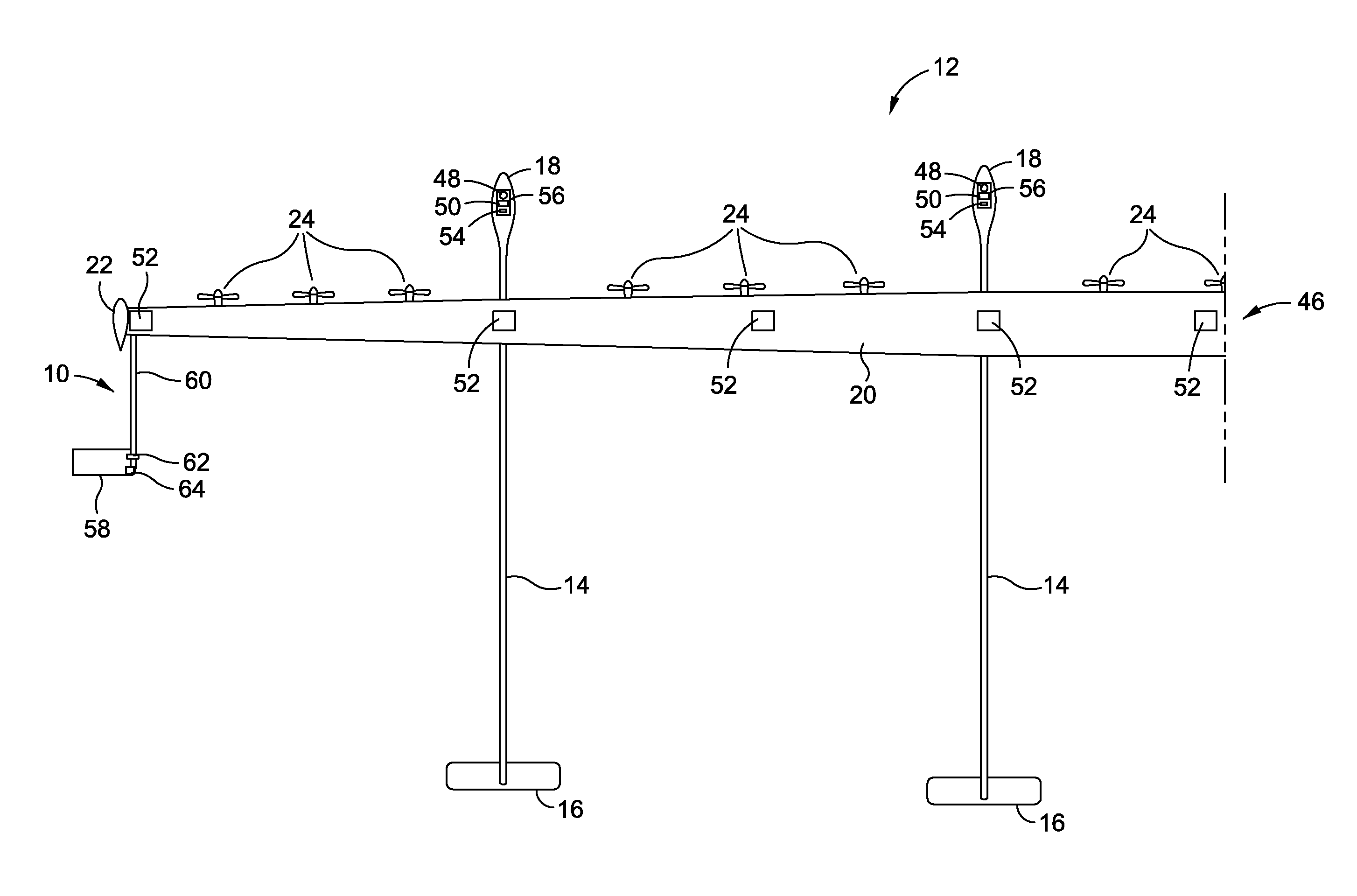
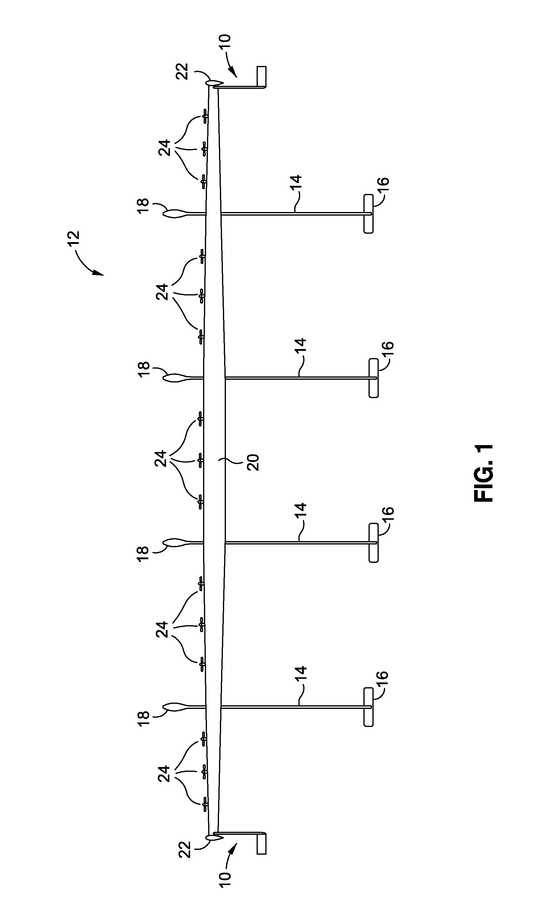
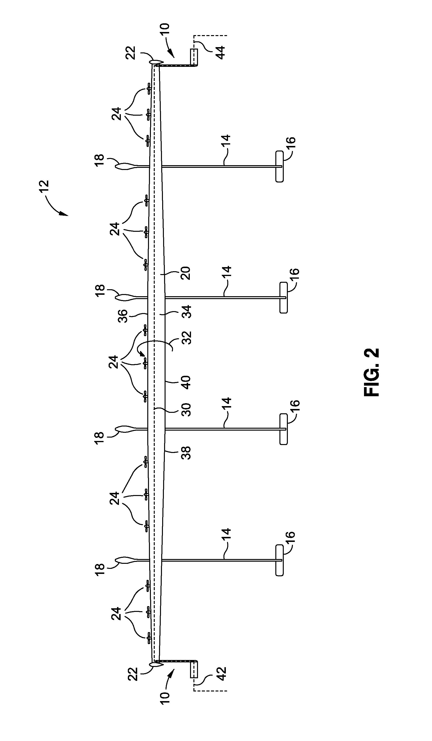
[0033]Now referring to the Figures, FIG. 1 shows an embodiment of a wing tip device 10 of the disclosure in use with an exemplary embodiment of an air vehicle 12. FIG. 1 is an illustration of a top view of the air vehicle 12 having the wing tip device 10. The air vehicle 12 is a multiple fuselage air vehicle having four (4) fuselages 14, four (4) tails 16, four (4) noses 18, a wing 20, two (2) wing tips 22, and fifteen (15) propulsion elements 24, such as, for example, in the form of motor propellers or an...


PUM


Abstract

The disclosure provides in one embodiment a wing tip device for a wing of an air vehicle. The device comprises a tip tail element, a boom element attaching the tip tail element to a wing tip, a hinge element connecting the tip tail element to the boom element, and an actuator element connected to the hinge element. One or more wing load sensors sense wing loads, and a flight control system controls the actuator element. A load alleviation method and system for an air vehicle are also provided.

Description

BACKGROUND[0001]1) Field of the Disclosure[0002]The disclosure relates generally to air vehicles, and more particularly, to wing tip devices for use on air vehicles.[0003]2) Description of Related Art[0004]Air vehicles, such as unmanned air vehicles, solar powered aircraft, non-solar powered aircraft, high altitude air vehicles, and commercial and military aircraft, can be susceptible to atmospheric turbulence, such as wind gust loads, which can significantly overload the wings. When an air vehicle is subjected to a sudden wind gust, wind gust loads may be created on a wing or wings of the air vehicle. Such wind gust loads can cause sudden variations in the wing angle of attack which can correspondingly cause sudden variations in the wing lift and can result in wing bending that can exceed the wing load.[0005]Devices exist that can be installed in an air vehicle wing to alleviate or reduce wind gust loads and control the wing bending resulting from such wind gust loads. For example,...

Claims


Application Information

Patent Timeline
Patent Type & Authority Patents(United States)
IPC IPC(8): B64C23/00
CPCB64C13/16Y02T50/44B64C2201/021B64C2201/042B64C2201/104B64C2201/162B64C2201/165Y02T50/40B64U10/25B64U50/19B64U30/10B64U50/14B64U50/13
Inventor MILLER, GERALD D.
Owner THE BOEING CO
Why Eureka
Try Eureka