
Forming mesh

a mesh and mesh technology, applied in the field of paper machine mesh, can solve the problems of reducing affecting the flatness of the mesh, and carrying a lot of water, so as to reduce the risk of delamination of the two fabric layers, reduce the thickness of the mesh and the disadvantages connected therewith, and the effect of a larger cross-section

Inactive Publication Date: 2009-12-29
VOITH PATENT GMBH
View PDF32 Cites 5 Cited by
  • Summary
  • Abstract
  • Description
  • Claims
  • Application Information

AI Technical Summary

Benefits of technology

The inventive paper machine mesh has binder threads that join the two fabric layers and bicycle threads that join the binder threads and the lower fabric layer. The lower fabric layer is formed by the binder threads, lower transverse threads, and lower longitudinal threads. The binder threads are arranged in pairs, and each pair is interchangingly woven with the lower transverse threads. The lower fabric layer has a weaving pattern repeated in lower repeats. The binder threads are woven with the lower longitudinal threads to form segments, which reduces the thickness of the mesh and prevents delamination of the fabric layers. The lower transverse threads form knuckles with the lower longitudinal threads, holding the tie segments firmly in position and reducing inner wear of the mesh. The lower fabric layer also has dewatering channels formed by the long floats of the lower transverse threads, reducing dewatering speed and tendency toward marking.

Problems solved by technology

The known meshes of said kind have the disadvantage that the lower fabric layer is tied at each tie-on point only by way of one warp thread to the upper fabric layer, as the result of which a high force acts on said warp thread and pulls it into the inside of the mesh, thus exerting a negative effect on the flatness of the mesh.
Furthermore, the binder threads on the known meshes of said kind often cover a large distance between the upper and the lower fabric layer, as the result of which the meshes known from the prior art are often very thick and therefore carry a lot of water.
In addition, the meshes known from the prior art often display a dewatering behavior which varies greatly over the mesh surface and can lead to hydraulic marking of the paper formed on such meshes.
Furthermore, on the known meshes the binder threads between the fabric layers are often exposed to high wear because often said threads are not sufficiently fixed between the fabric layers.

Method used


Image

  • Forming mesh
  • Forming mesh
  • Forming mesh

Examples


first embodiment

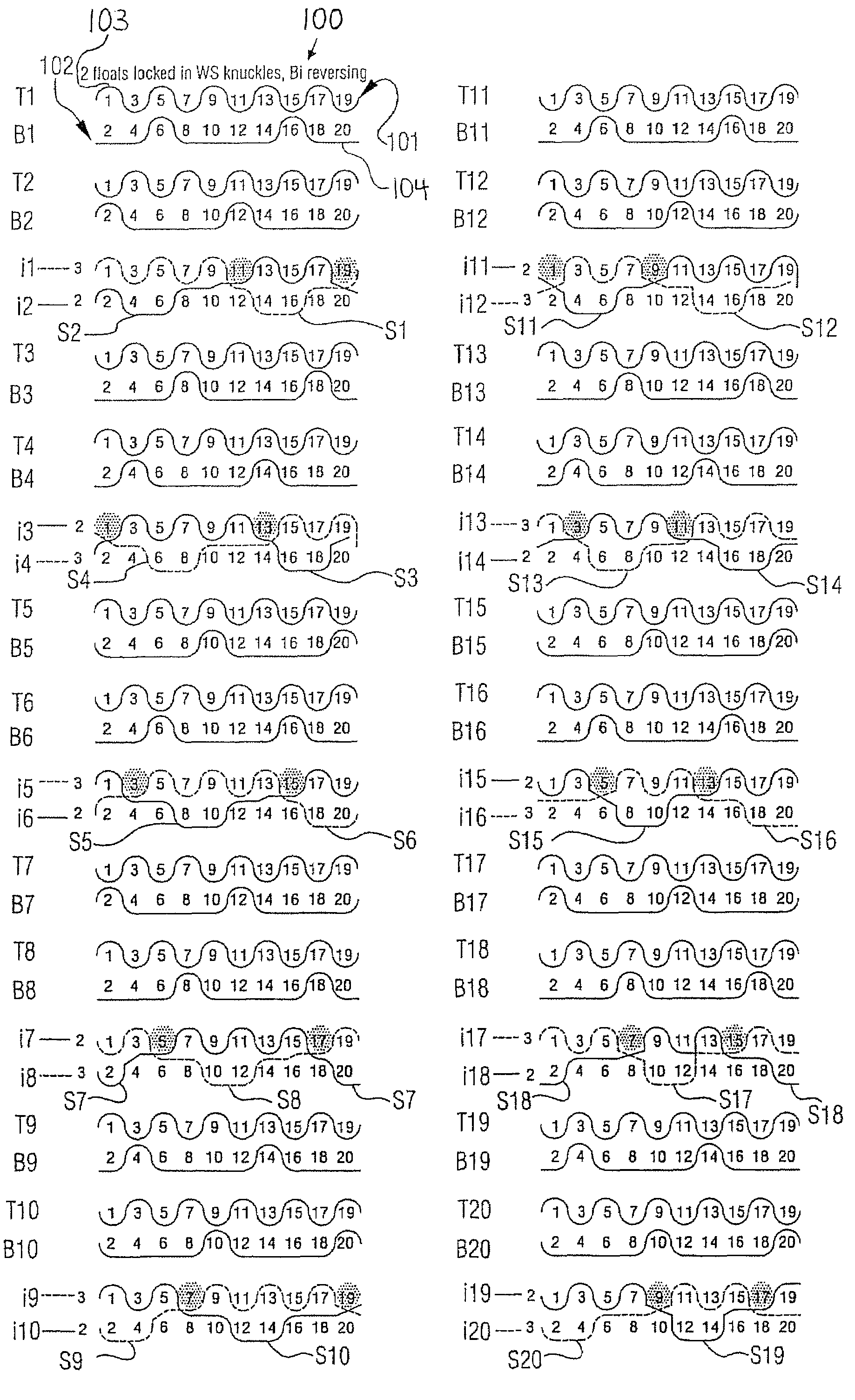
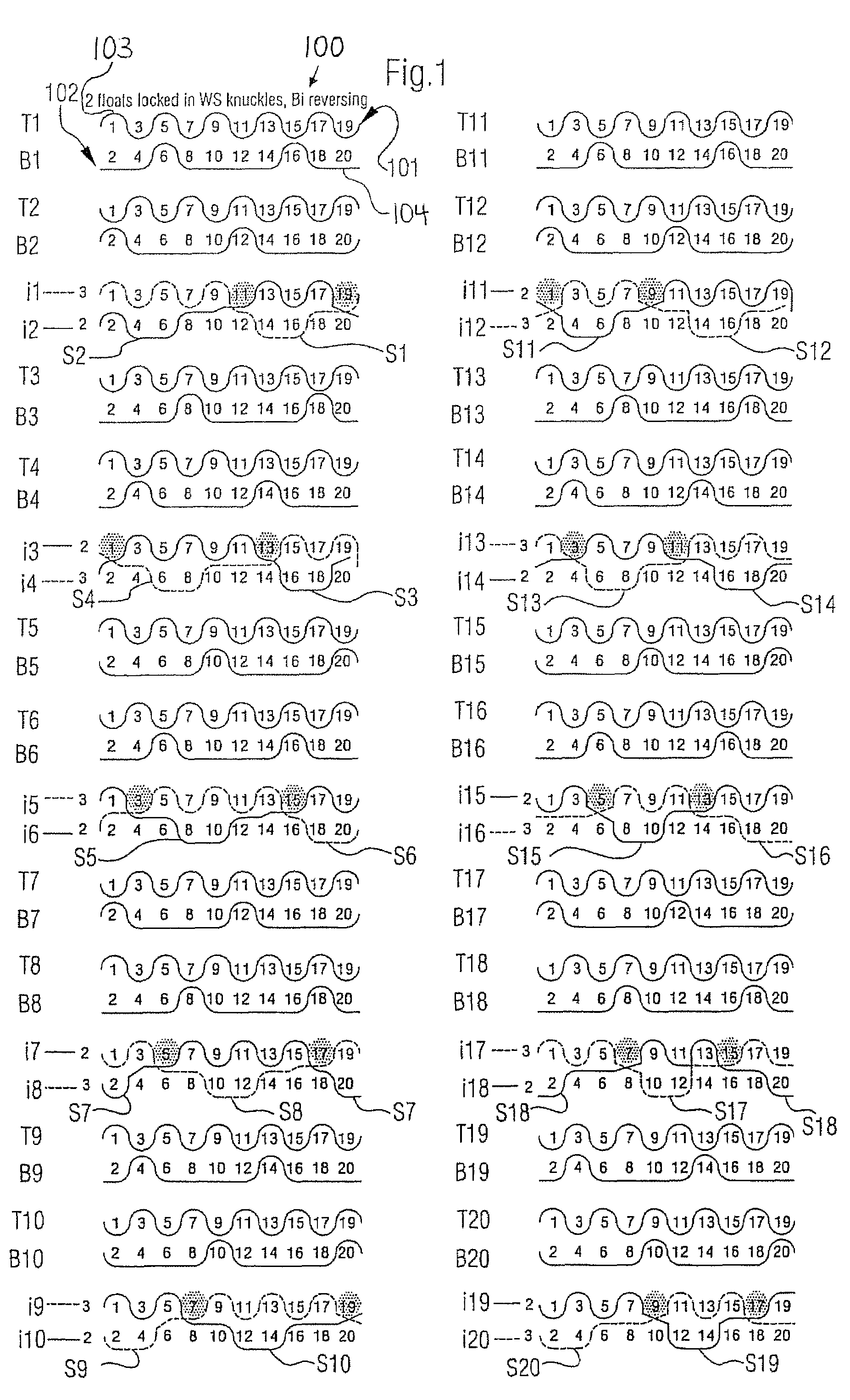
[0029]Referring now to the drawings, and more particularly to FIG. 1, there is shown, in the transverse thread direction, an inventive paper machine mesh 100 constructed as a forming mesh. In the representation in FIG. 1 there is shown a repeat unit of the weave structure of the mesh 100.

[0030]The forming mesh 100 has upper longitudinal threads 1,3,5,7,9,11,13,15,17 and 19 constructed as warp threads and lower longitudinal threads 2,4,6,8,10,12,14,16,18 and 20 constructed as warp threads. The longitudinal threads extend in this case perpendicularly from the drawing plane of FIG. 1.

[0031]Furthermore, the forming mesh 100 has binder threads it to i20 which are arranged in binder thread pairs i1 and i2, i3 and i4 to i19 and i20.

[0032]Also, the forming mesh 100 has upper transverse threads T1 to T20 constructed as weft threads and lower transverse threads B1 to B20 constructed as weft threads. On the forming mesh 100 presented in FIG. 1, the ratio of the number of binder thread pairs i1...

second embodiment

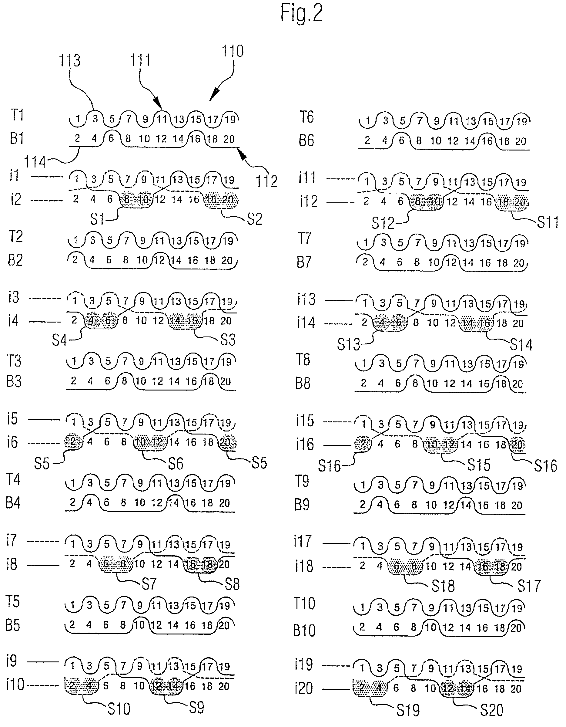
[0056]FIG. 2 shows an inventive paper machine mesh 110 constructed as a forming mesh.

[0057]The mesh 110 presented in FIG. 2 differs essentially from the forming mesh 100 presented in FIG. 1 in that the ratio of the number of binder thread pairs i1 and i2 to i19 and i20 and upper transverse threads T1 to T10 together to the number of lower transverse threads B1 to B10 is 2:1. Mesh 100 includes the outer side 113 of the upper fabric layer 111 and the outer side 114 of the lower fabric layer 112.

[0058]Furthermore, tie segments formed by binder threads of the same kind from directly adjacent binder thread pairs are—unlike in FIG. 1—directly adjacent each other in the transverse thread direction. This means that for example the binder threads of a first kind i2, i3, i6, i7, i10, i11, i14, i15, i18 and i19 form together with the corresponding lower transverse threads the tie segments S2, S3, S6, S7, S10, S11, S14, S15, S18 and S19, whereby for example the tie segments S2 and S3, which are...


PUM


Abstract

A paper machine mesh, in particular a forming mesh, includes an upper and a lower fabric layer and binder threads to join the two fabric layers, the lower fabric layer having a weaving pattern which is repeated in lower repeats. Within the lower repeat, each binder thread of each pair with lower longitudinal threads forms at least one tie segment and each tie segment is formed in that the respective binder thread of the pair continually crosses two or more directly consecutive lower longitudinal threads on the outer side of the lower fabric layer, and the tie segments of each binder thread pair are arranged relative to the lower transverse threads flanking said segments.

Description

BACKGROUND OF THE INVENTION[0001]1. Field of the Invention[0002]This invention relates to a paper machine mesh, in particular a forming mesh.[0003]2. Description of the Related Art[0004]Forming meshes are used in the forming section of a paper machine. During the forming process, a fiber suspension from the headbox of the paper machine is applied to one forming mesh or to two forming meshes (in the case of gap formers). It is an object of the forming mesh in this case to dewater the fiber suspension and to form a fibrous web, whereby as little cellulose fiber and filler material as possible should be separated from the fiber suspension during the dewatering process.[0005]The quality of the formed fibrous web is co-defined in this case to a great extent by the structure of the surface of the forming mesh facing the fibrous web (paper side). The life of the forming mesh, on the other hand, is greatly influenced by the structure of the surface of the forming mesh facing the paper machi...

Claims


Application Information

Patent Timeline
Patent Type & Authority Patents(United States)
IPC IPC(8): D03D3/04D21F7/08D03D23/00D03D25/00
CPCD21F1/0045
Inventor BOECK, JOHANN
Owner VOITH PATENT GMBH
Learn More