Fluid collection and drain pan with integrated strength-enhancing structure

a technology of strength-enhancing structure and drain pan, which is applied in the direction of defrosting, domestic cooling apparatus, etc., can solve the problems of float switch malfunction and fluid leakage, extra expense for installers, and risk of overflow or back-up into the system, so as to save installers the cost of purchasing, resist permanent deformation, cracking, and/or weakening materials

Inactive Publication Date: 2009-12-29
RECTORSEAL LLC
View PDF20 Cites 21 Cited by
  • Summary
  • Abstract
  • Description
  • Claims
  • Application Information

AI Technical Summary

Benefits of technology

[0006]It is the primary object of this invention to provide a fluid-collecting pan of sturdy construction for use in long duration, stable, and pre-leveled support of a liquid-level float switch and fluid drain assembly in its originally installed position for reliable repeated operation, as needed, to turn off fluid production in a fluid-producing system supported upon the pan when fluid accumulation in the pan exceeds a pre-established threshold amount considered safe. It is also an object of this invention to provide a fluid collection pan that is not unit-dedicated, and can be used with multiple sizes and configurations of fluid-producing units to save installers the expense of purchasing and storing a multitude of unit-dedicated pans for their installations. It is a further object of this invention to provide a fluid collection pan with strengthening features that allow it to effectively fulfill its intended fluid collection function while resisting permanent deformation, cracking, and / or weakening of materials as a result of installer manipulation, as well as that resulting from pre-installation handling during transport and storage. A further object of this invention is to provide a fluid collection pan that is sufficiently rugged for upright fluid-producing units in small spaces. It is also an object of this invention to provide a fluid collection pan that enables stable pan installation, facilitates pan and float switch installation, shortens pan and float switch installation time, and requires minimal post-installation inspection and maintenance. A further object of this invention is to provide a fluid collection pan with a nesting structure for efficient transport and storage of multiple pans in stacked array. In addition, it is a further object of the present invention to provide a fluid collecting pan made from corrosion-resistant materials that resist premature deterioration and malfunction, as well as materials resistant to temperature extremes for installation in 140-degree attics and unheated basements, utility rooms, or garages.

Problems solved by technology

When air conditioning and / or furnace condensate and other condensates are collected, there is often a risk of overflow or back-up into the system producing it.
Some are made from materials that deform in hot attics, resulting in float switch malfunction and fluid leakage.
Also, there are different sizes of fluid-producing units, many times requiring the use of different sizes of pan, which causes extra expense to installers by requiring them to purchase and store multiple sizes of pan in advance of installations.
Further, when an installer or repairman works with a prior art fluid collection pan that is unit-dedicated, the installers and repairmen have the added expense of maintaining a supply of at least several different kinds of float switches, some adapting better to the thinner upper edge of metal condensate collection pans, and others more suited to the variable thicknesses found in existing plastic condensate collection pans.
In addition, prior art fluid collection pans are often large and may need to be elevated or placed in a tight space, such as during attic installations.
As a result fluid-collection pans are at risk for bending and / or being stepped on one or more times by the installer.
If the materials used a fluid-collection pan are thin or weak in any way, it will be subject to cracks and weak spots, which are likely to cause fluid leakage and require premature replacement.

Method used


Image

  • Fluid collection and drain pan with integrated strength-enhancing structure
  • Fluid collection and drain pan with integrated strength-enhancing structure
  • Fluid collection and drain pan with integrated strength-enhancing structure

Examples


Embodiment Construction

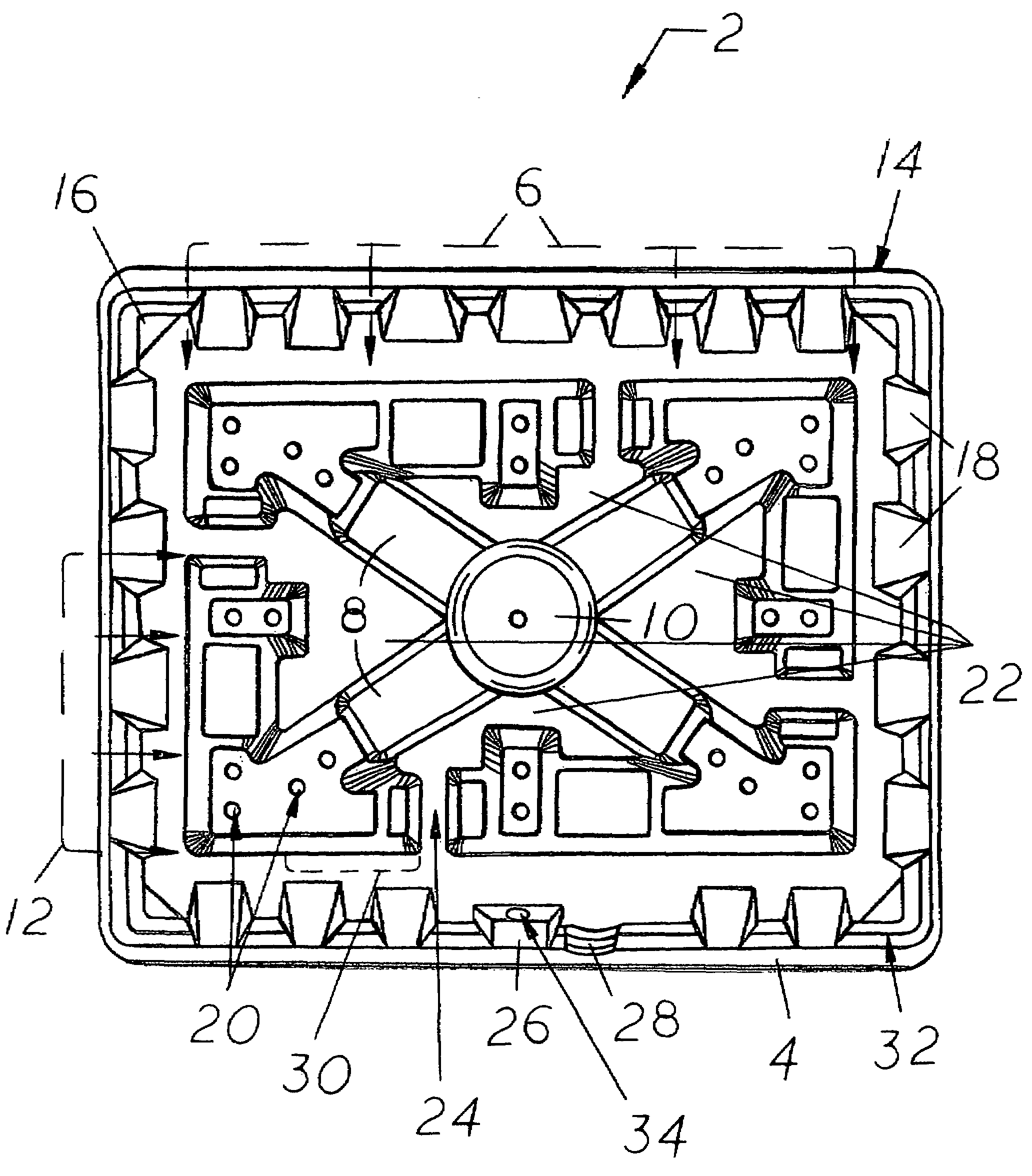
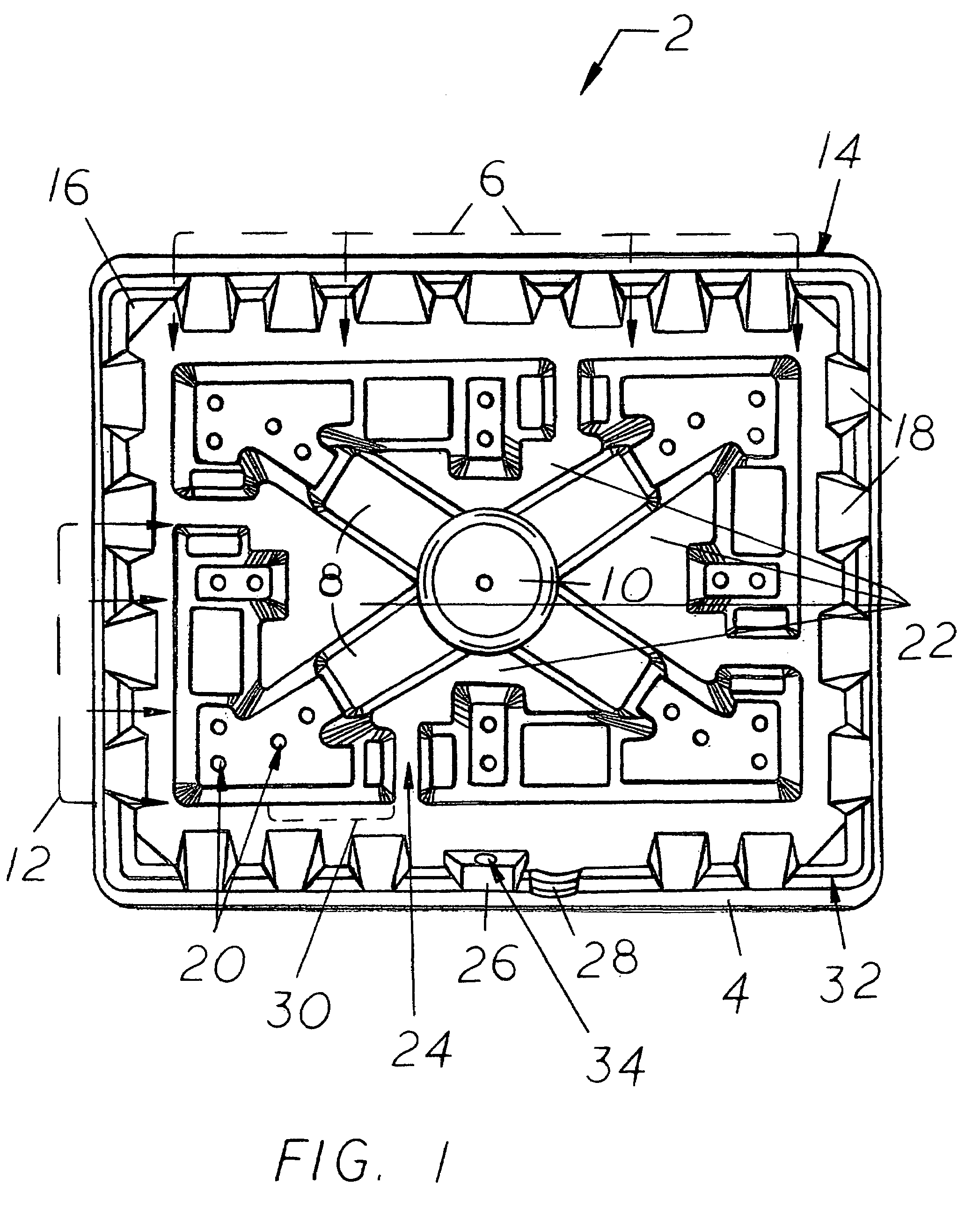
[0016]While FIGS. 1-7 reveal the structure of the most preferred embodiment 2 of the present invention, it is to be understood that many variations in the present invention are possible. Those that are not patentably distinct from the most preferred embodiment 2 disclosed herein are also considered to be within the scope of, and a part of, the present invention, even though they may not be specifically mentioned or shown. As a result, a reader should determine the scope of the present invention by the appended claims. FIGS. 1-4 show the most preferred embodiment 2 of the present invention, while FIGS. 5-7 show preferred configurations of a vibration isolator 36 that can be used as a part of the present invention.

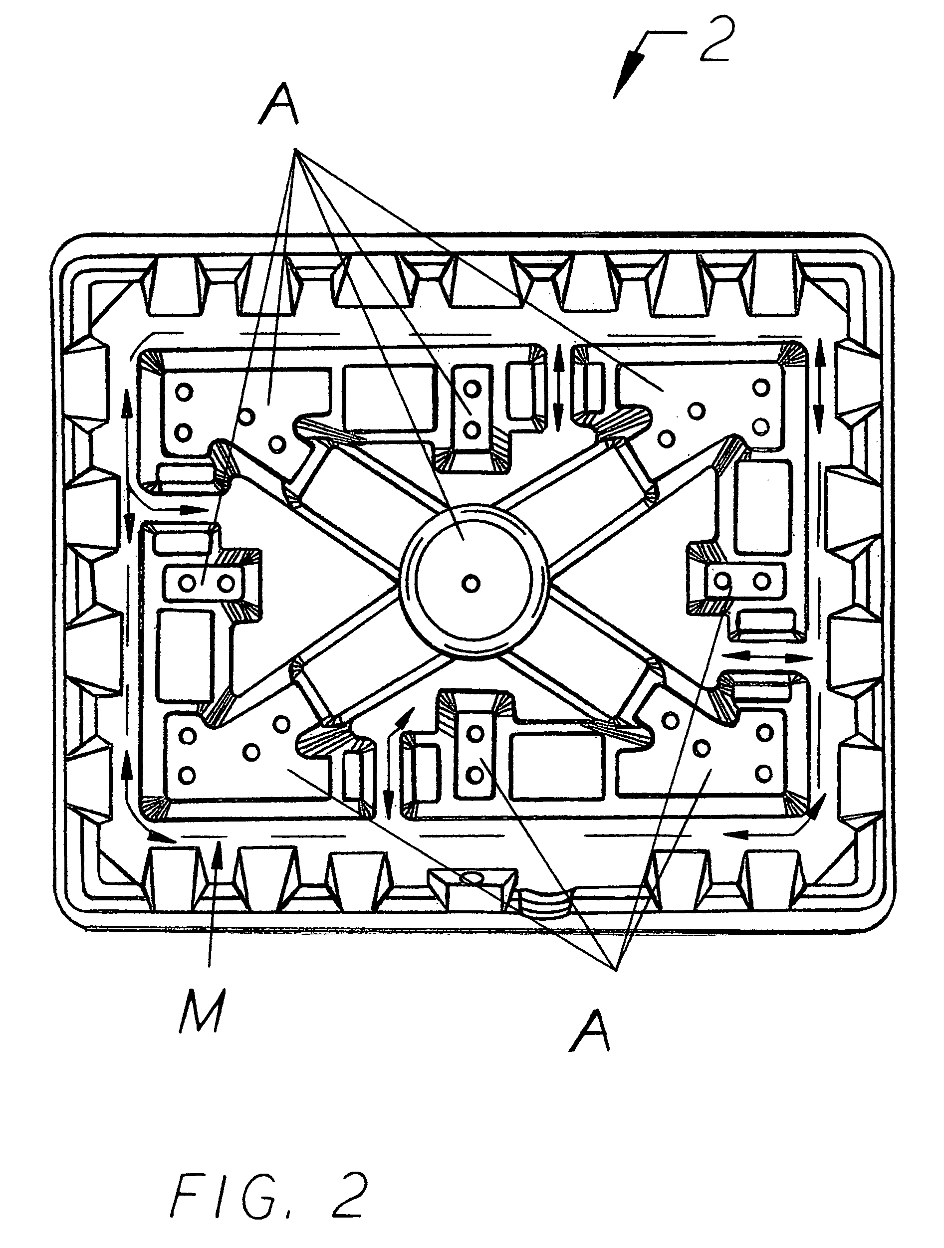
[0017]FIGS. 1-3 show top views of the most preferred embodiment 2 of the present invention fluid collection and drain pan, with FIG. 1 identifying present invention components by number, FIG. 2 identifying by the letter “A” highly raised portions of the bent distal ends 12 a...


PUM


Abstract

A one-size-fits-all pan configured for supporting a fluid-producing unit. It has a perimeter wall spaced apart from a raised central structure to provide a moat-like area for flow of collected fluid toward a wall-mounted shut-off switch. When a desired maximum amount of fluid collection is exceeded, an electrical signal is sent to stop fluid production. The raised central structure comprises a hub with radially-extending ribs that each widens into a bent distal end having non-uniform height and width dimensions, and top indentations for receipt of vibration isolators that support the fluid-producing unit at a height above that of the perimeter wall. The non-raised areas around the ribs are all connected to the moat-like area to facilitate even fluid distribution within the pan. The pan further has an up-turned perimeter lip, staggered gussets, and angled corners for added strength, and may optionally have a nesting configuration for compact storage and transport.

Description

CROSS-REFERENCES TO RELATED APPLICATIONS[0001]None.BACKGROUND[0002]1. Field of the Invention[0003]This invention relates to fluid collection pans used in association with a fluid or condensate producing or system such as a commercial or residential air conditioning system as well as those used to prevent damage caused by leaks in fluid-holding containers, such as a hot water heater, specifically to a one-size-fits-all fluid-collecting pan or tray (hereinafter usually referred to only as “pan”) having a generally raised central structure substantially filling its center portion and a surrounding perimeter wall at a spaced-apart distance from the central structure to provide a moat-like area for the movement of collected fluid toward a float switch mounted on the perimeter wall, which if deployed will send a shut-off signal to the fluid-producing unit associated with the pan when a predetermined threshold amount of collected fluid considered safe is exceeded. The raised central struct...

Claims


Application Information

Patent Timeline
Patent Type & Authority Patents(United States)
IPC IPC(8): B65D1/36B65D1/34F25D21/14
CPCF25D21/14F25B2500/13F25D2500/02
Inventor CANTOLINO, CHRISTOPHER RALPH
Owner RECTORSEAL LLC
Why Eureka
Try Eureka