Electrical connector

a technology of electrical connectors and connectors, applied in the direction of coupling contact members, coupling device connections, securing/insulating coupling contact members, etc., can solve the problems of increased production costs, achieve high contact reliability, reduce production costs, and facilitate production

Inactive Publication Date: 2009-12-29
ORMON CORP
View PDF5 Cites 18 Cited by
  • Summary
  • Abstract
  • Description
  • Claims
  • Application Information

AI Technical Summary

Benefits of technology

[0008]Accordingly, in the aspect of the present invention, because the second connector is attached after the plug is molded, the insert molding is not required. Therefore, the metal mold can easily be made to reduce the production cost.
[0010]In the electrical connector according to an embodiment of the present invention, preferably lateral slippage is prevented by press-fitting the substantially U-shaped press-fitting portions of the second connector in the plural substantially U-shaped press-fitting grooves provided in parallel along an outer peripheral surface of the opening edge portion of the plug body.
[0011]Accordingly, looseness is eliminated in the lateral direction of the second connector to obtain the electrical connector having the high assembly accuracy and higher contact reliability.
[0016]Accordingly, the outer peripheral surface of the side wall of the plug body is substantially flush with the outer peripheral surface of the press-fitting portion of the second connector, so that the assembly work can smoothly be performed in assembling the plug in the socket.

Problems solved by technology

Therefore, higher dimensional accuracy is required for a metal mold with downsizing apparatus, and it takes a long time to make the metal mold, which results in a problem in that production cost is increased.

Method used


Image

  • Electrical connector
  • Electrical connector
  • Electrical connector

Examples


Embodiment Construction

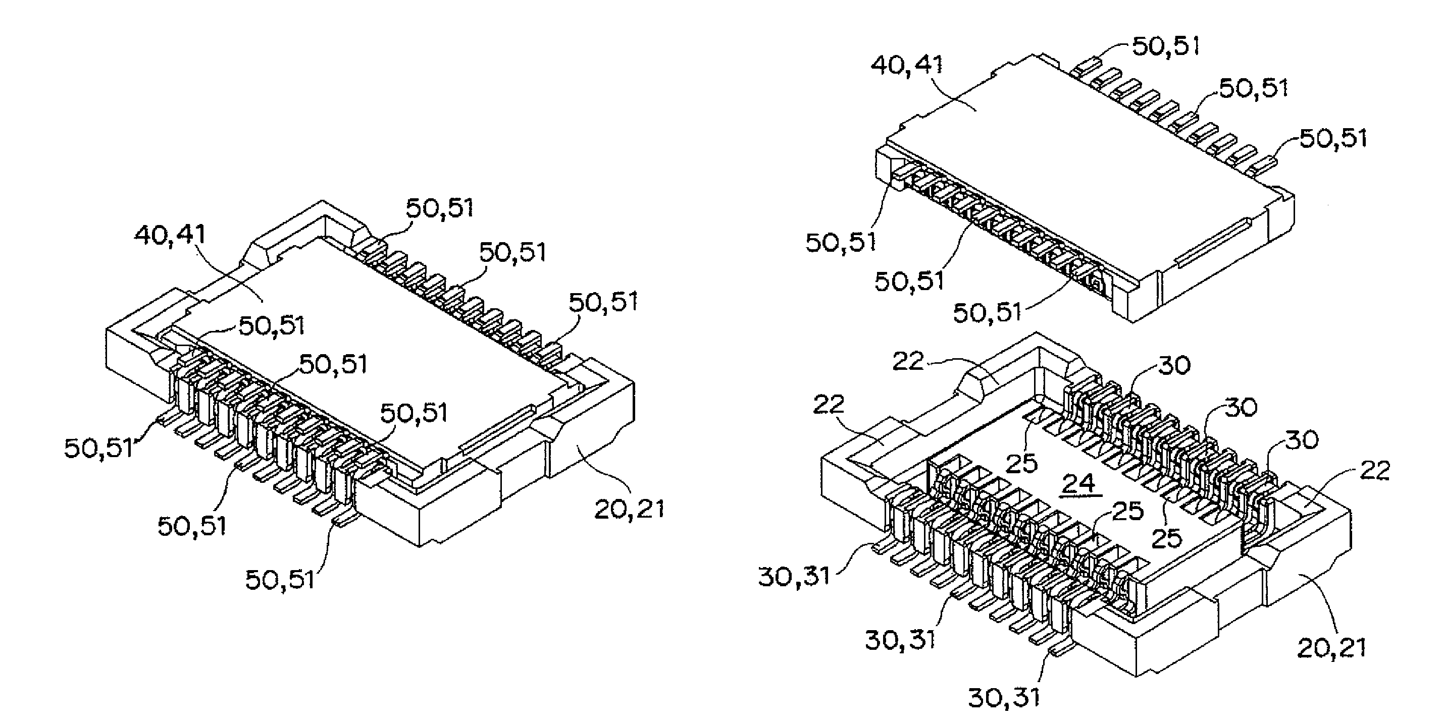
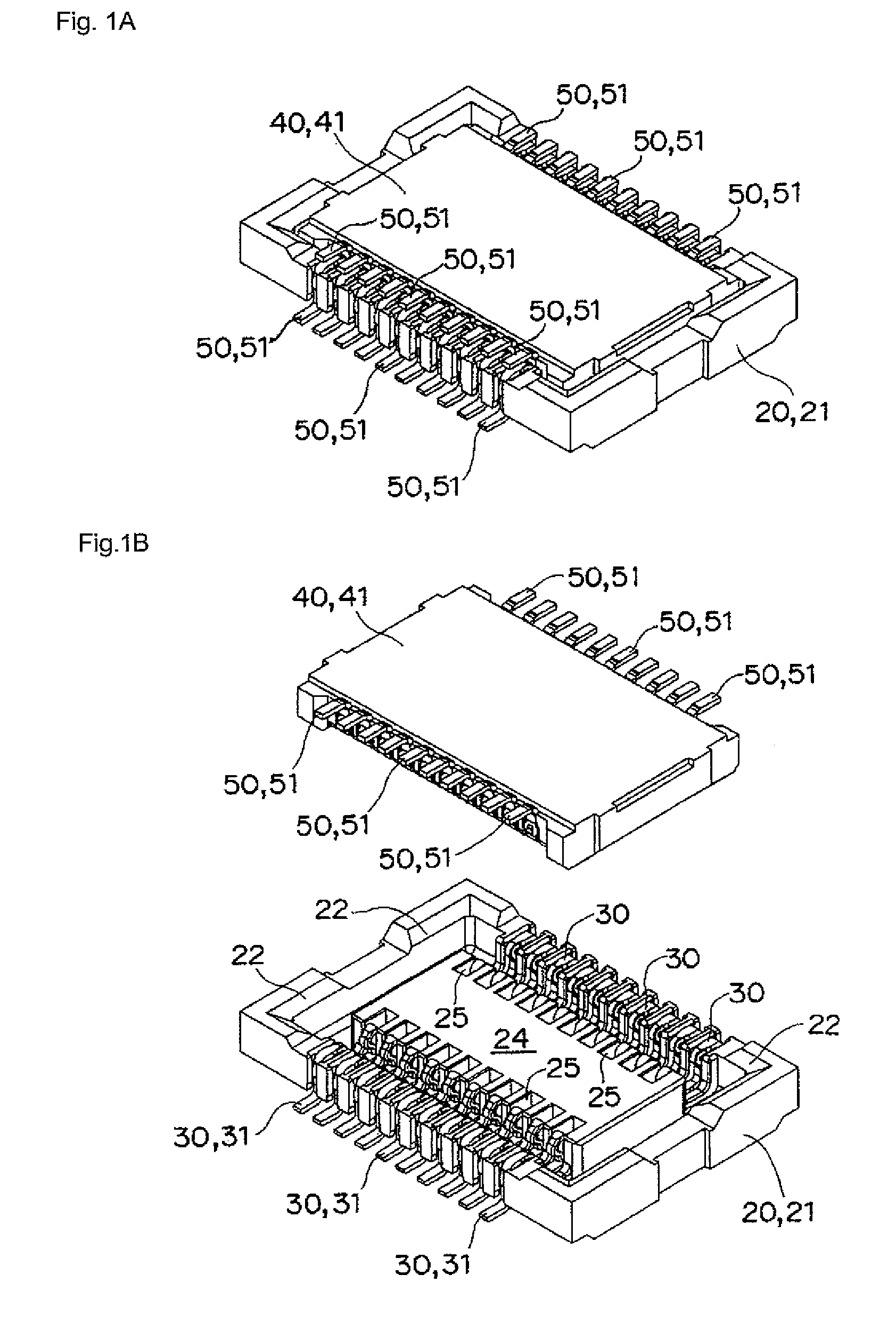
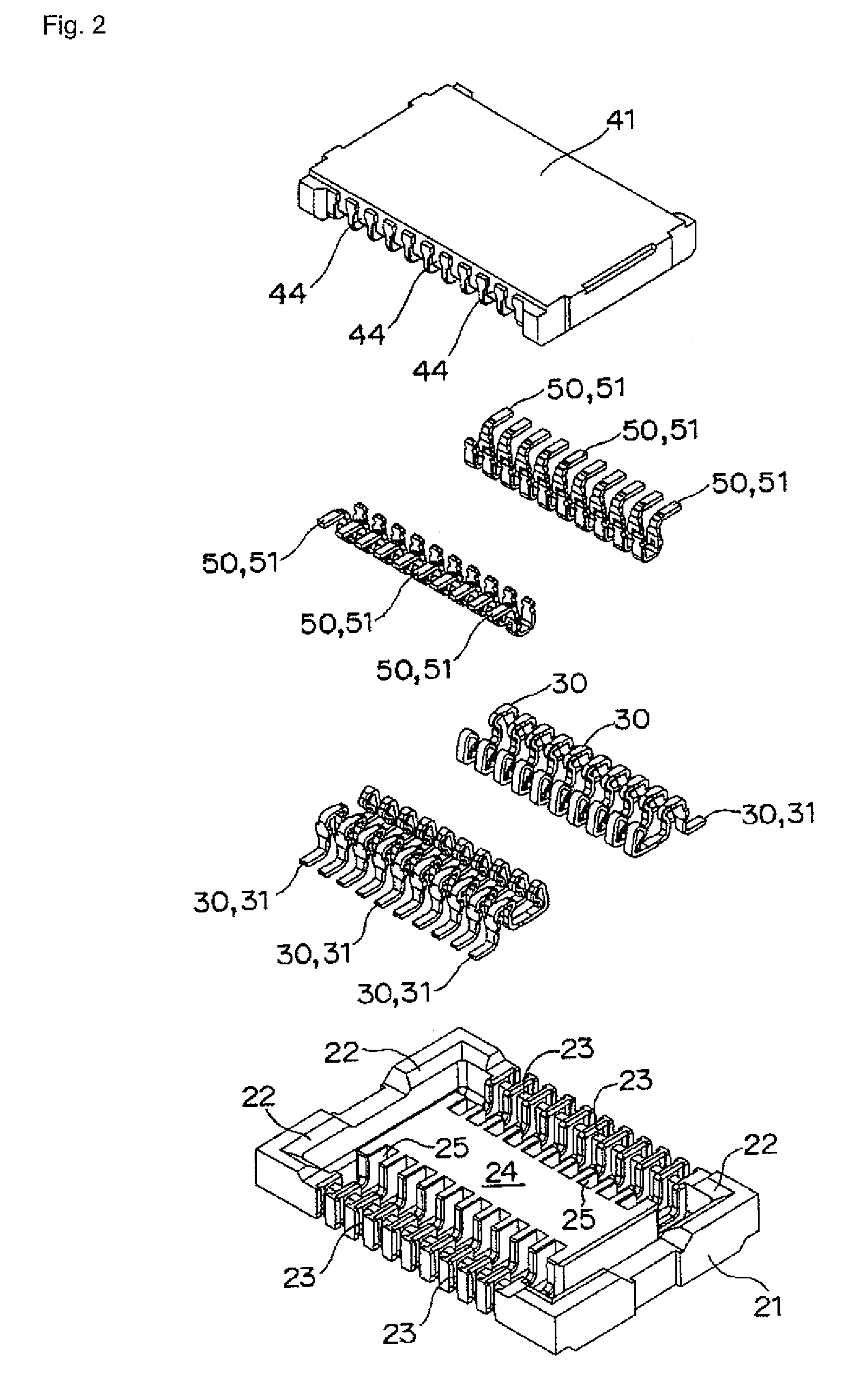
[0031]An electrical connector according to an embodiment of the present invention will be described with reference to the accompanying drawings, FIGS. 1 to 12. As shown in FIGS. 1 to 10, the electrical connector of the embodiment includes a socket 20 connected to an upper surface of a printed wiring board 10 and a plug 40 connected to a lower surface of a printed wiring board 11.

[0032]As shown in FIGS. 3, 4, and 5, in the socket 20, plural first connectors 30 are provided in parallel along opening edge portions facing each other in a socket body 21. As shown in FIG. 3, the socket body 21 is formed in a box shape having a shallow bottom, guiding tapered surfaces 22 are formed in the opening edge portions, and substantially U-shaped press-fitting grooves 23 are provided in parallel at predetermined intervals. First connectors 30, which will be described later, are press-fitted in the substantially U-shaped press-fitting grooves 23 along outer peripheral surfaces of side walls facing e...


PUM


Abstract

An electrical connector includes a socket and a plug. In the socket, plural first connectors are provided in parallel, and substantially U-shaped press-fitting portions are assembled so as to cross over opening edge portions of a socket body. In the plug, plural second connectors are provided in parallel, and substantially U-shaped press-fitting portions are assembled so as to cross over opening edge portions of a plug body. The plug body has a planar shape which can be fitted in the opening edge portions of the socket body. Particularly, a free end portion of the press-fitting portion of the second connector located in the opening edge portion of the plug body is engaged with a position regulating recess formed in a bottom surface of the plug body.

Description

BACKGROUND OF THE INVENTION[0001]1. Field of the Invention[0002]The present invention relates to an electrical connector, particularly to an electrical connector electrically connecting printed circuit boards to each other.[0003]2. Description of the Related Art[0004]Conventionally, in the electrical connector, a header 12 rigidly connected to a lower surface of a printed circuit board A is fitted in a socket 11 rigidly connected to an upper surface of another printed circuit board A, and a contact terminal 14 provided in the socket 11 is elastically brought into contact with a contact terminal 16 provided in the header 12, thereby connecting the printed circuit boards to each other (refer to, for example, Japanese Patent Application Laid-Open No. 2005-203139).[0005]However, in the conventional electrical connector, plural contact terminals 16 are provided in parallel in the header 12 by insert molding. Therefore, higher dimensional accuracy is required for a metal mold with downsiz...

Claims


Application Information

Patent Timeline
Patent Type & Authority Patents(United States)
IPC IPC(8): H01R24/00
CPCH01R4/028H01R12/716H01R13/41H01R12/73H01R13/10
Inventor HOSHINO, HIROKAZUKIMURA, NAOYUKISHIMURA, YUSUKE
Owner ORMON CORP
Why Eureka
Try Eureka