Endoprosthesis for controlled contraction and expansion

a technology of endoprosthesis and expansion balloon, which is applied in the field of endoprosthesis, can solve the problems of limited deliverability performance, difficult access to the intended deployment site, and retention of the expansion balloon, and achieve the effect of reducing the risk of recurren

Inactive Publication Date: 2009-12-29
ABBOTT LAB INC
View PDF149 Cites 31 Cited by
  • Summary
  • Abstract
  • Description
  • Claims
  • Application Information

AI Technical Summary

Benefits of technology

[0028]In a preferred method of expanding an endoprosthesis, the endoprosthesis has both a contractile portion and an expansive portion positioned on a balloon of an endoprosthesis delivery catheter. The balloon is inflated to an intermediate endoprosthesis diameter that is less than the fully expanded diameter thereof. In this manner, the balloon causes the endoprosthesis to expand only to the in...

Problems solved by technology

Additionally, the intended deployment site is often difficult to access by a physician and involves traversing the delivery system through the tortuous pathway of the anatomy.
High scaffolding stents employ a relatively large amount of metal, and this metal can restrict how tightly the stent can be crimped, thus limiting its profile, retention on an expansion balloon, and deliverability performance.
The deliverability of a stent device can be also limited by the amount of material at the distal en...

Method used


Image

  • Endoprosthesis for controlled contraction and expansion
  • Endoprosthesis for controlled contraction and expansion
  • Endoprosthesis for controlled contraction and expansion

Examples


embodiment 54

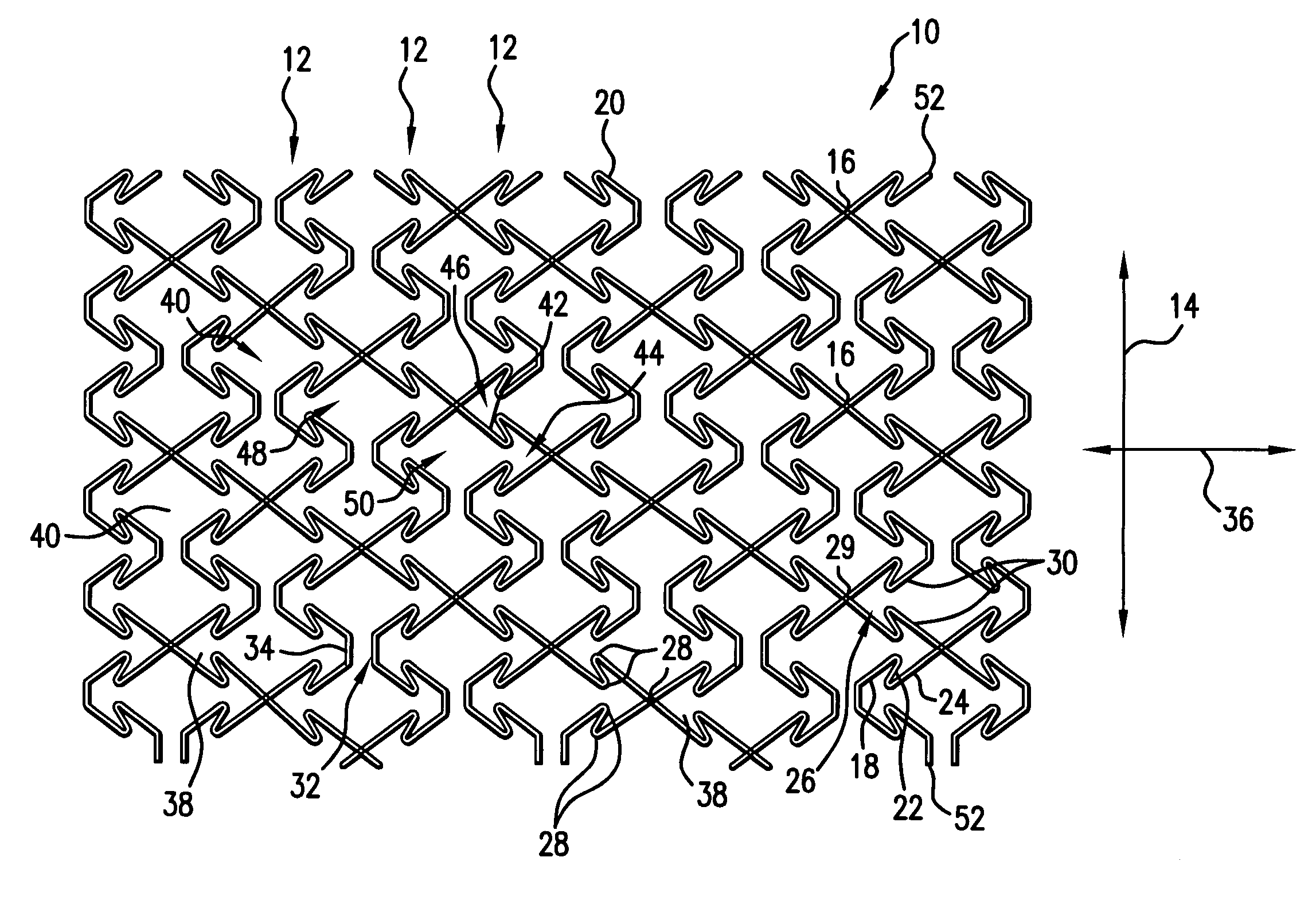
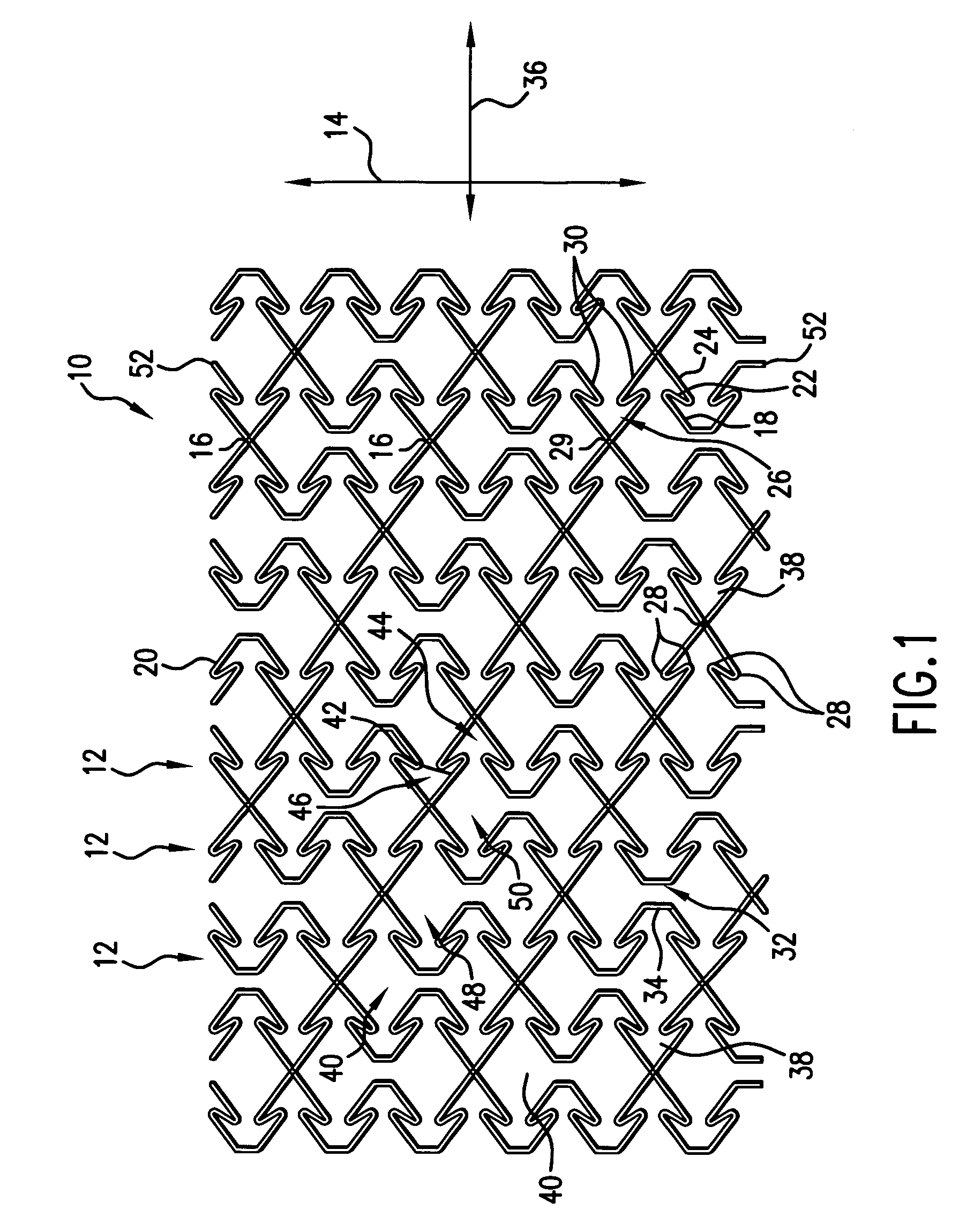
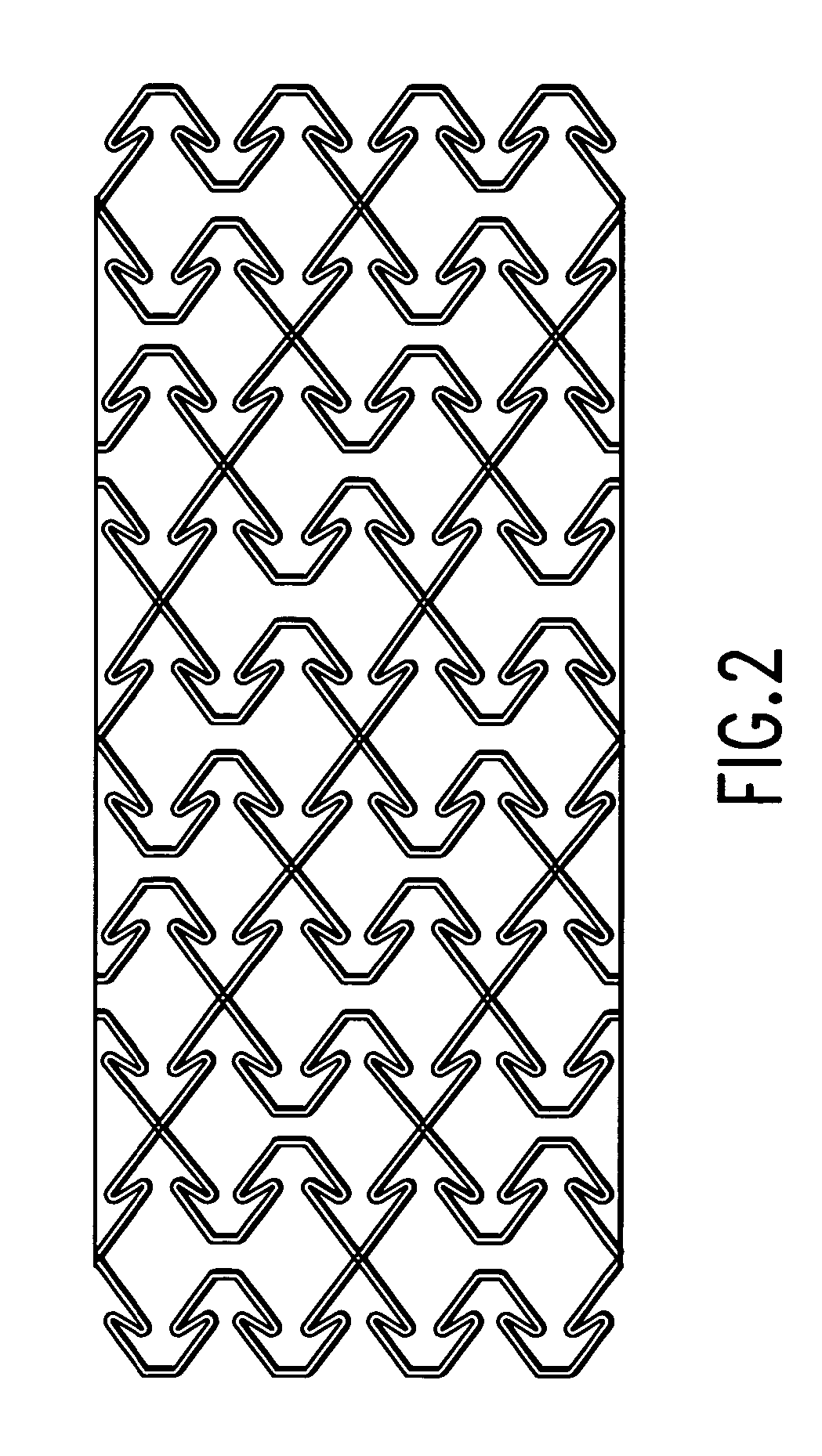
[0064]The preferred stent is substantially cylindrical, and the circumferential edges of the stent 10 are preferably continuous with each other. In an alternative embodiment, the stent is made of a coiled sheet, in which the lateral edges of the pattern are not affixed to each other and in which the annular elements 12 are open. The coiled sheet can be delivered in a small diameter, coiled state to the deployment site, with the opposing edges of the sheet preferably configured for engaging each other when the stent is expanded to the deployed position, to prevent collapse of the stent. For example, uneven lateral edges can be used on the opposite circumferential edges 56 to hook with each other to prevent collapse. FIG. 3 shows a coiled sheet embodiment 54, with saw tooth circumferential edges 56 to catch in interlocking engagement with opposing saw tooth circumferential edges 56 to prevent collapse of the sheet from the deployed position. In this manner, the coil sheet will both un...

embodiment 322

[0095]The annular element 312 shown in FIGS. 28 and 29 for purpose of illustration and not limitation has cells 314 that include expansive sections 316 fixed to contractile sections 318, preferably at hinge points 320. FIGS. 30 and 31 show another stent embodiment 322 with cells 324 that incorporate both expansive sections 326 and contractile sections 328 that are naturally biased opposite each other. In both of these embodiments, the expansive sections 316,326 preferably each have an elongated shape generally aligned in a longitudinal direction 330, and contractile sections 318,328 each have an S-shape or folded shape that extends generally in a circumferential direction 332. When moved from the contracted state to the expanded state, the expansive sections preferably expand circumferentially, and the contractile sections preferably expand circumferentially as well as longitudinally, with the S-shape uncoiling.

[0096]In the embodiment of FIGS. 30 and 31, the contractile sections 328...


PUM


Abstract

An endoprosthesis that has an interconnected series of struts, selected strut members connected to adjacent strut members at a longitudinal apex. Strut members include a first end portion, an intermediate portion hingedly connected to the first end portion, and a second end portion hingedly connected to the intermediate portion and extending to the apex. Some of the strut members can have a nesting feature configured for nestingly receiving another strut member when the endoprosthesis is in the delivery condition. A scaffolding body of the endoprosthesis can have an inner and outer component, each having a set of interconnected strut members which overlap those of the other to define a cooperating cell pattern. Also, the endoprosthesis can be configured to naturally tend to contract when the body is smaller than a predetermined diameter and expand when the body is larger than a predetermined diameter.

Description

CROSS-REFERENCE TO RELATED APPLICATIONS[0001]This application claims the benefit of Provisional Patent Application No. 60 / 378,278, filed May 6, 2002; No. 60 / 378,279, filed May 6, 2002; No. 60 / 378,345, filed May 8, 2002; and No. 60 / 379,310, filed May 8, 2002; the content of each application is expressly incorporated herein by reference thereto.FIELD OF THE INVENTION[0002]The present invention relates to an endoprosthesis having delivery and deployed configurations for implantation into a vessel. More particularly, the invention relates to a stent with improved contraction and expansion characteristics.BACKGROUND OF THE INVENTION[0003]Stents, grafts and a variety of other endoprostheses are well known and used in interventional procedures, such as for treating aneurysms, for lining or repairing vessel walls, for filtering or controlling fluid flow, and for expanding or scaffolding occluded or collapsed vessels. Such endoprostheses can be delivered and used in virtually any accessible ...

Claims


Application Information

Patent Timeline
IPC IPC(8): A61F2/06A61F2/90
CPCA61F2/91A61F2/915A61F2002/91508A61F2002/91533A61F2220/0075A61F2002/91558A61F2002/91566A61F2210/0076A61F2002/9155
Inventor PAPPAS, JEFFCLIFFORD, ANTON G.CRYER, BRETT
Owner ABBOTT LAB INC
Why Eureka
Try Eureka