Stator arrangement and rotor arrangement for a transverse flux machine

a technology of transverse flux and rotor, which is applied in the direction of dynamo-electric machines, magnetic circuit rotating parts, magnetic circuit shape/form/construction, etc., can solve the problems of complex and costly process of building the rotor using a plurality of single magnets or the subsequent magnetization of a ring magnet, and achieves easy magnetization unipolar, greater output power, and greater magnet volume

Inactive Publication Date: 2009-12-29
MINEBEAMITSUMI INC
View PDF13 Cites 47 Cited by
  • Summary
  • Abstract
  • Description
  • Claims
  • Application Information

AI Technical Summary

Benefits of technology

[0023]The rotor arrangement according to the invention makes it possible to realize a rotor that is based on an easily magnetized unipolar ring magnet. The remanence of the magnetic material can be optimally exploited making it possible to accommodate a greater magnet volume, so that a transverse flux machine having correspondingly greater output power can be produced. As a whole, the rotor arrangement is superior to known rotor arrangements for transverse flux machines where magnetization and the optimal exploitation of the magnet volume is concerned. The claw pole design ensures that the ring magnet is simultaneously protected and fixed.
[0024]The invention also provides a transverse flux machine which combines the described stator arrangement and the described rotor arrangement to form one phase of the machine. The stator arrangement and the rotor arrangement are disposed coaxially with respect to one another and the pole c...

Problems solved by technology

This may mean that constructing the rotor using a plurality of single magnets or magnetizing a ring magnet accordingly would be a very ...

Method used


Image

  • Stator arrangement and rotor arrangement for a transverse flux machine
  • Stator arrangement and rotor arrangement for a transverse flux machine
  • Stator arrangement and rotor arrangement for a transverse flux machine

Examples


Embodiment Construction

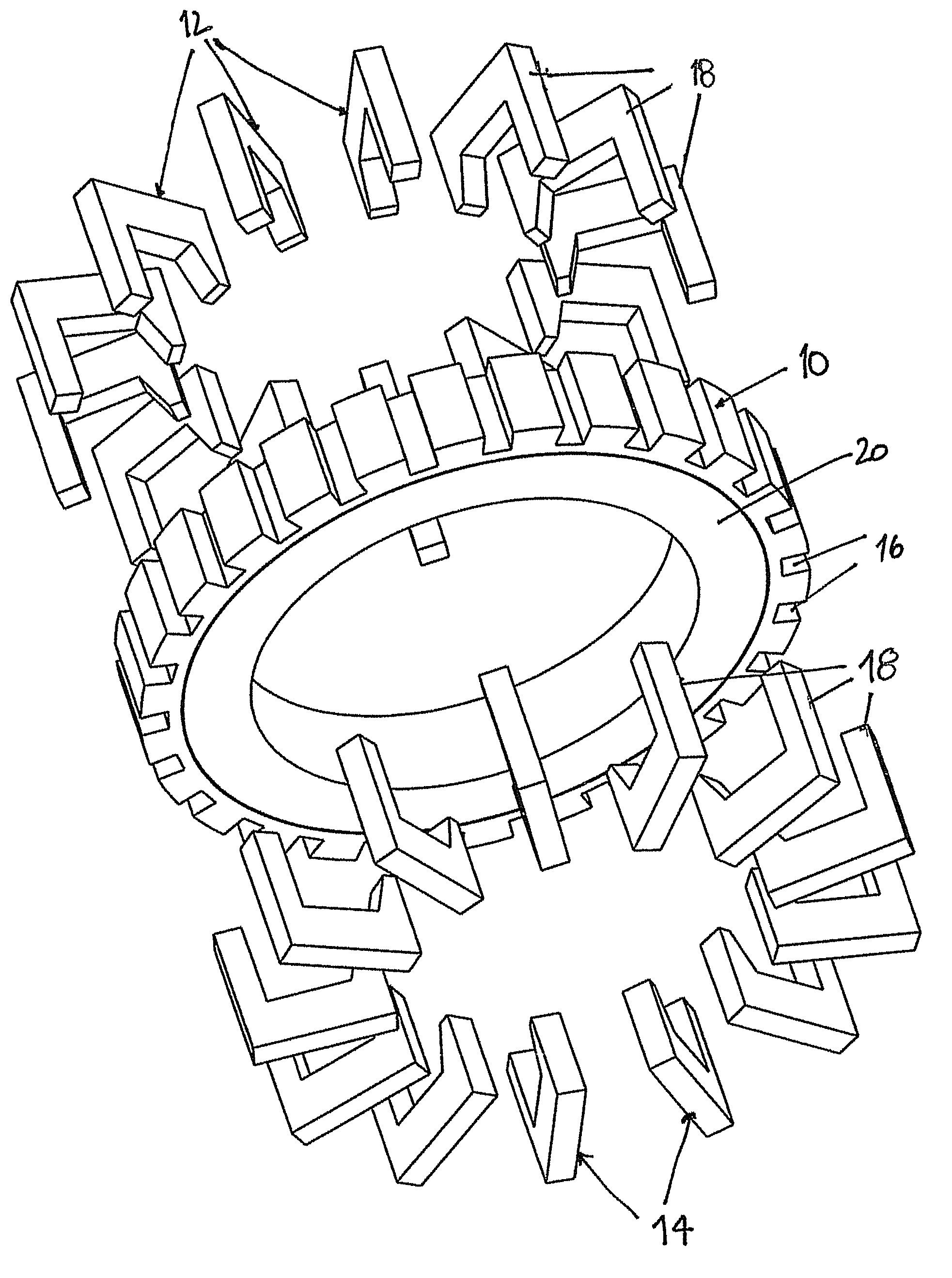
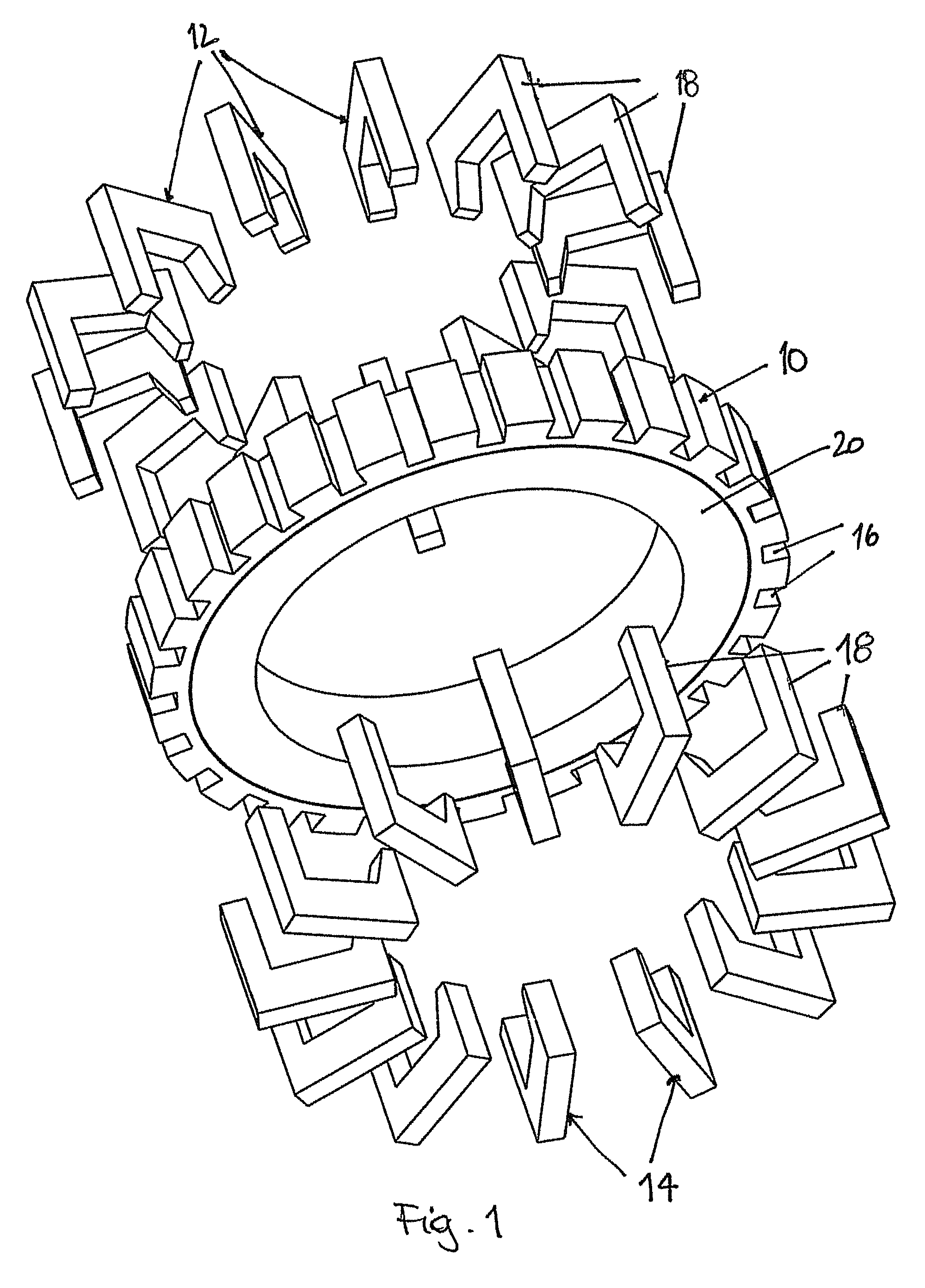
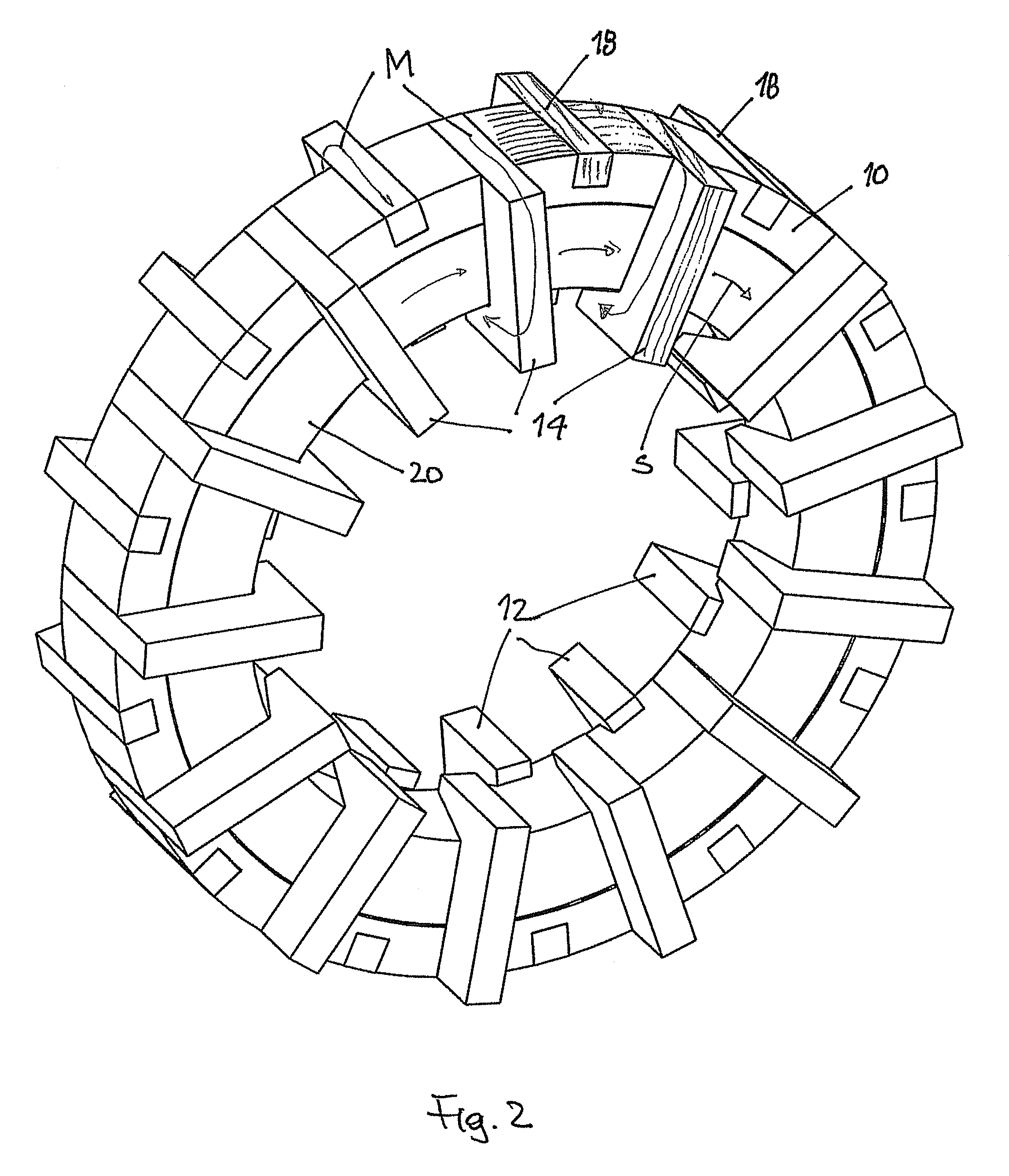
[0040]FIG. 1 shows a perspective, exploded view of a advantageous embodiment of the stator arrangement according to the invention. The stator arrangement comprises an annular stator back yoke 10 as well as a plurality of stator poles 12, 14 that are designed in the manner of claw poles, one half of the stator poles 12 being mounted onto the stator back yoke 10 from one end face of the stator back yoke 10 and the other half of the stator poles 14 being mounted from the opposite end face of the stator back yoke 10. To this effect, recesses 16 are formed in the outside circumference of the stator back yoke 10 into which corresponding projections 18 that are integrally formed on the stator poles 12, 14 engage. The connection is preferably effected using an interference fit. The stator poles encompass a winding 20 that is schematically shown in FIG. 1 as a ring. FIG. 2 shows the stator arrangement according to the invention after the stator poles 12, 14 have been inserted into the stator...


PUM


Abstract

A stator arrangement and a rotor arrangement for a transverse flux machine. The stator arrangement comprises an annular stator back yoke having a number of stator poles designed in the manner of claw poles. The rotor arrangement includes number of rotor poles designed in the manner of claw poles and connected to each other to form an annular rotor body enclosing a unipolar ring magnet magnetized in an axial direction. In the stator arrangement, the stator back yoke includes a first laminated stack of metal sheets whose laminations are stacked in an axial direction, and the stator poles include a second laminated stack of metal sheets whose laminations are stacked in a tangential direction. In the rotor arrangement, the rotor poles include laminated stacks of metal sheets whose laminations are stacked in a tangential direction.

Description

[0001]This application claims priority to the filing date of German Patent Application No. 10 2006 022 836.7 filed May 16, 2006 the disclosure of which is incorporated herein by reference.[0002]The invention relates to a stator arrangement as well as a rotor arrangement for a transverse flux machine wherein the stator poles and / or rotor poles are designed in the manner of claw poles.BACKGROUND[0003]U.S. Pat. No. 6,492,758 describes an electronically commutated transverse flux motor having a multiple phase stator. The stator is formed from two complementary facing pieces each carrying half the stator poles that are designed in the manner of claw poles. The stator windings are sandwiched between these two pieces and are encompassed by the opposing claw poles. In this document, the advantages of transverse flux machines are touched on briefly. A transverse flux machine is capable of producing power densities that are several times greater than conventional radial flux machines. This ar...

Claims


Application Information

Patent Timeline
IPC IPC(8): H02K1/12
CPCH02K1/145H02K21/145H02K1/2713H02K21/227
Inventor PULNIKOV, ANDREYKLOEPZIG, MARKUSBORSAI, PETER
Owner MINEBEAMITSUMI INC
Why Eureka
Try Eureka