Flicker reduction method, flicker reduction circuit and image pickup apparatus

a flicker reduction and flicker reduction technology, applied in the field of flicker reduction methods and flicker reduction circuits, can solve the problems of inability to detect flickering and the disadvantage of increasing the circuit dimensions, so as to prevent the image quality from being degraded, reduce flicker, and correct flicker

Inactive Publication Date: 2009-12-29
SONY CORP
View PDF21 Cites 10 Cited by
  • Summary
  • Abstract
  • Description
  • Claims
  • Application Information

AI Technical Summary

Benefits of technology

[0012]Therefore, it is desirable to prevent degradation of image quality from taking place by correcting flicker without using a plurality of areas in an image and correcting by using values detected in the past without the risk of correcting flicker by error if a moving subject exists in the scene.
[0017]Thus, according to the present invention, it is possible to detect and correct the flicker of a fluorescent lamp specific to XY address scanning type imaging elements, which may typically be CMOS elements, regardless of the subject being shot, the video signal level and the type of the fluorescent lamp and reduce erroneous corrections due to a moving subject without using a light receiving element and a plurality of areas. Therefore, it is possible to correct flicker by using values detected in the past without erroneous corrections and prevent the image quality from being degraded by flicker even when the moving subject exists.

Problems solved by technology

However, when a moving subject comes into the scene to occupy the entire area of the picked up image, it is no longer possible to detect flickering because there is no still part in the image.
Additionally, since the above-described arrangement uses a plurality of areas produced by dividing an image, it is accompanied by a disadvantage of increasing the circuit dimensions.

Method used


Image

  • Flicker reduction method, flicker reduction circuit and image pickup apparatus
  • Flicker reduction method, flicker reduction circuit and image pickup apparatus
  • Flicker reduction method, flicker reduction circuit and image pickup apparatus

Examples


Embodiment Construction

[0036]Now, preferred embodiments according to the present invention will be described in greater detail by referring to the accompanying drawings. However, the present invention is by no means limited to the embodiments described below, which may be modified and altered in various different ways without departing from the spirit and scope of the present invention.

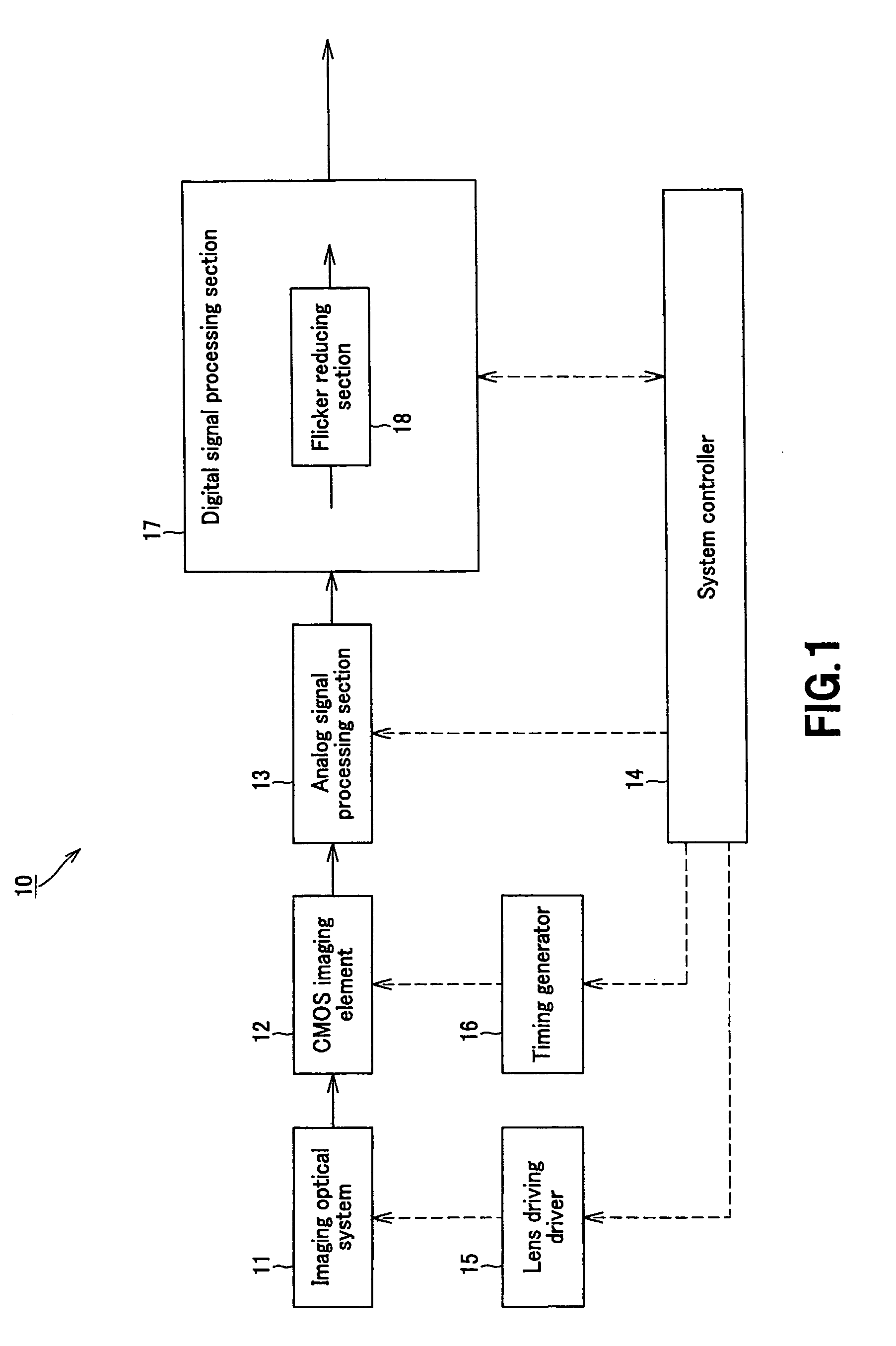
[0037]For example, the present invention is applicable to an image pickup apparatus having a configuration shown in FIG. 1.

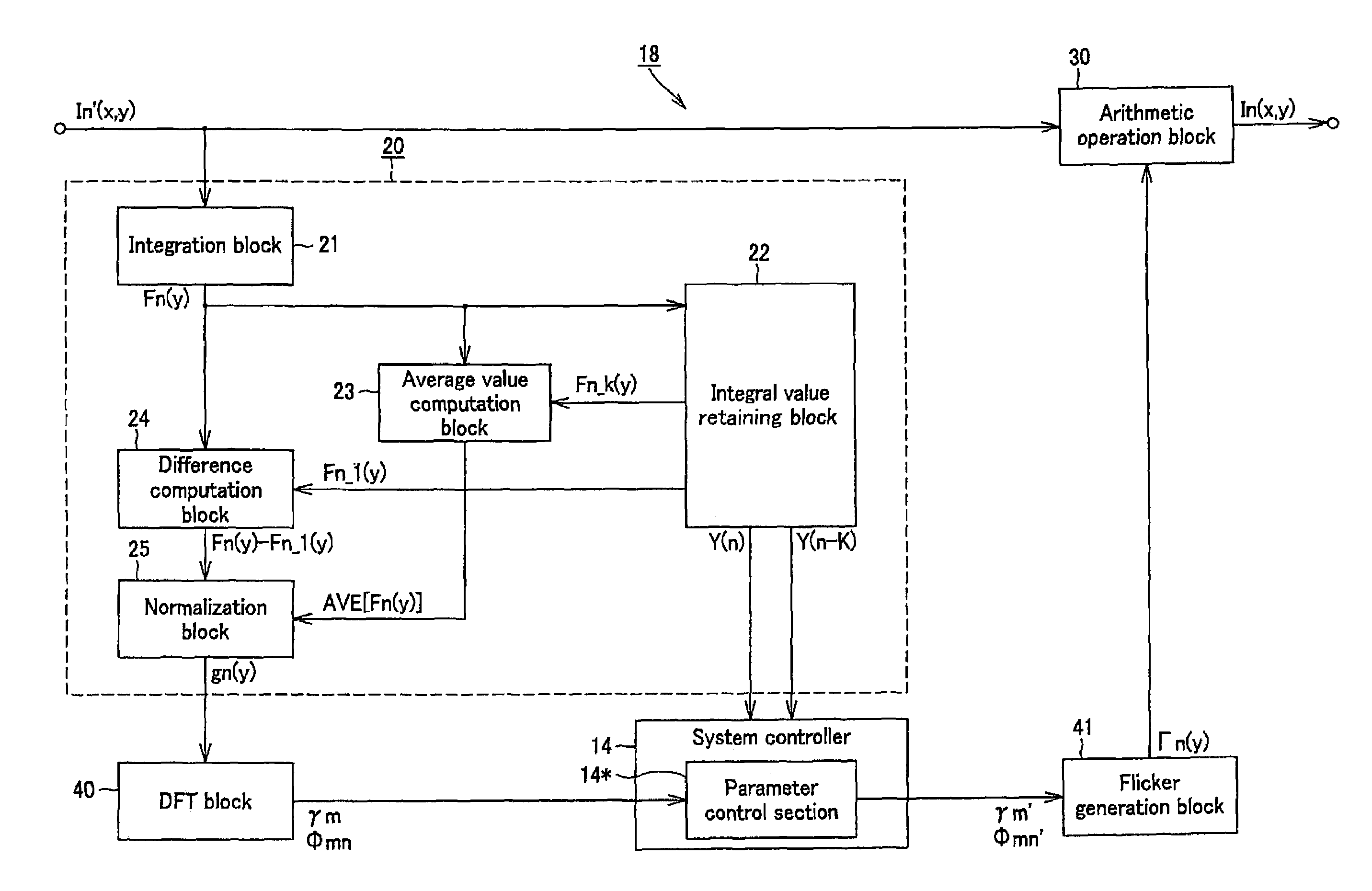
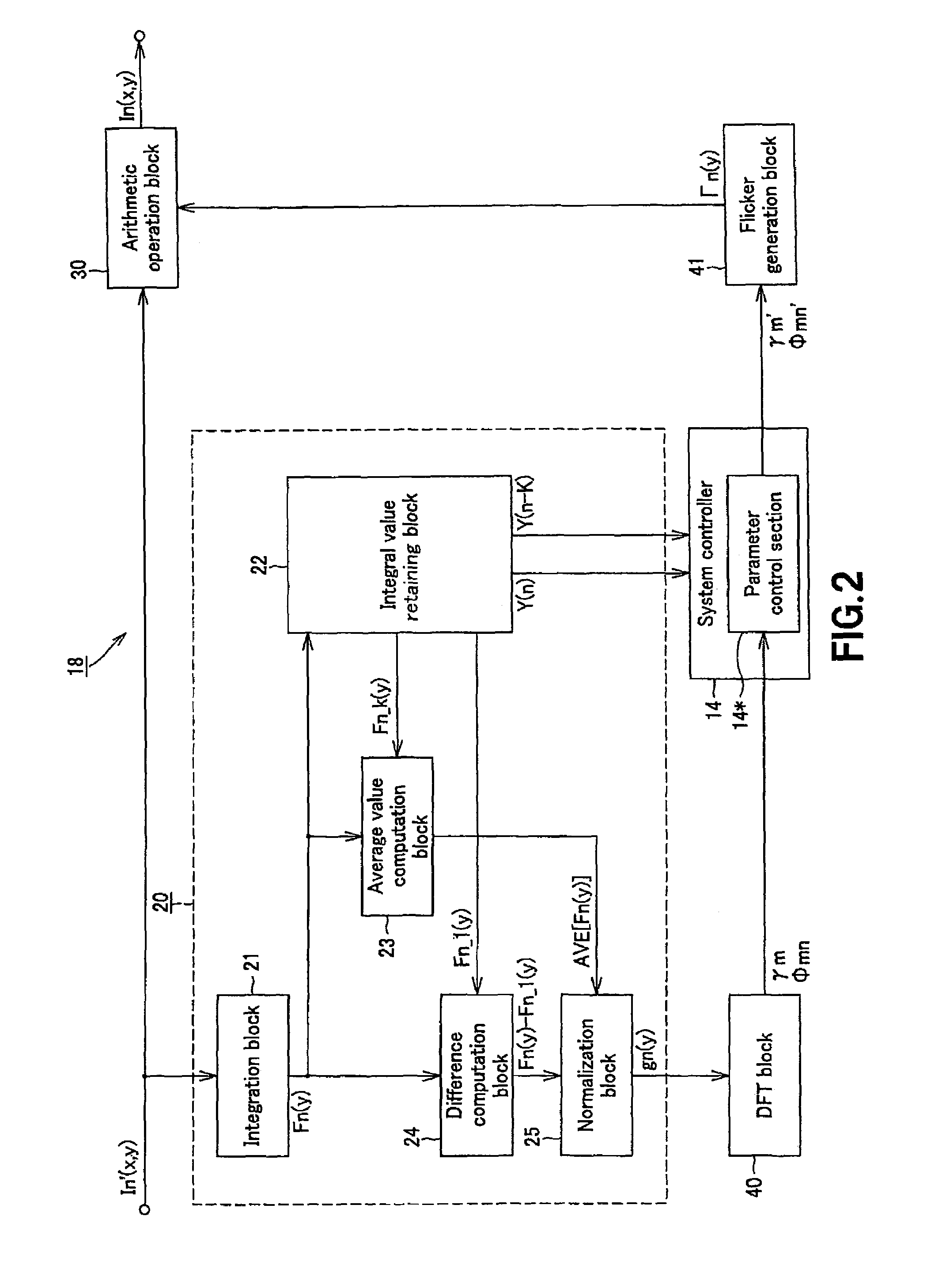
[0038]Referring to FIG. 1, the image pickup apparatus 10 is a video camera realized by using an XY address scanning type imaging element, which is a CMOS imaging element 12. The image pickup apparatus 10 includes an imaging optical system 11, a CMOS imaging element 12, an analog signal processing section 13, a system controller 14, a lens driving driver 15, a timing generator 16 and a digital signal processing section 17.

[0039]With this image pickup apparatus 10, light from a subject enters the CMOS ima...


PUM


Abstract

It is now possible to correct flicker without the risk of correcting flicker by error if a moving subject exists in the scene by using values detected in the past in order to prevent degradation of image quality from taking place. The integral value obtained by integrating an input video signal that includes a flicker component over not less than a horizontal period and the difference value between integral values of adjacent fields or frames is normalized. Then, the amplitude component and the phase component of the flicker component are estimated. A flicker coefficient for canceling the amplitude component and the phase component of the flicker component estimated is generated on the basis of the probability of being under the lighting of a fluorescent lamp. The flicker coefficient and the input video signal are computationally determined to obtain a video signal with a reduced flicker component.

Description

CROSS REFERENCES TO RELATED APPLICATIONS[0001]The present invention contains subject matter related to Japanese Patent Application JP 2005-261095 filed in the Japanese Patent Office on Sep. 8, 2005, the entire contents of which being incorporated herein by reference.BACKGROUND OF THE INVENTION[0002]1. Field of the Invention[0003]The present invention relates to a flicker-reduction method and a flicker-reduction circuit to be used for an image pickup apparatus such as a video camera or a digital still camera including an XY address scanning type imaging element (imager, image sensor), which may typically be a CMOS (complementary metal oxide semiconductor) imaging element, under the lighting of a fluorescent lamp and also to an image pickup apparatus adapted to use such a method and such a circuit.[0004]2. Description of the Related Art[0005]When an image of a subject is picked up by means of a video camera in direct light from a fluorescent lamp energized by a commercial AC power sup...

Claims


Application Information

Patent Timeline
Patent Type & Authority Patents(United States)
IPC IPC(8): H04N9/73H04N5/243
CPCH04N5/2357H04N5/235H04N23/745H04N23/70H04N25/60H04N25/76
Inventor NOMURA, HIROFUMIITO, MASAHIRO
Owner SONY CORP
Why Eureka
Try Eureka