Resistive memory cells and devices having asymmetrical contacts

a memory cell and asymmetric contact technology, applied in the field of magnetic resistance memory devices, can solve the problems of increased distance between neighboring memory cells, difficult etching, heat resistance metal, etc., and achieve the effect of good switching operation characteristics

Active Publication Date: 2009-12-29
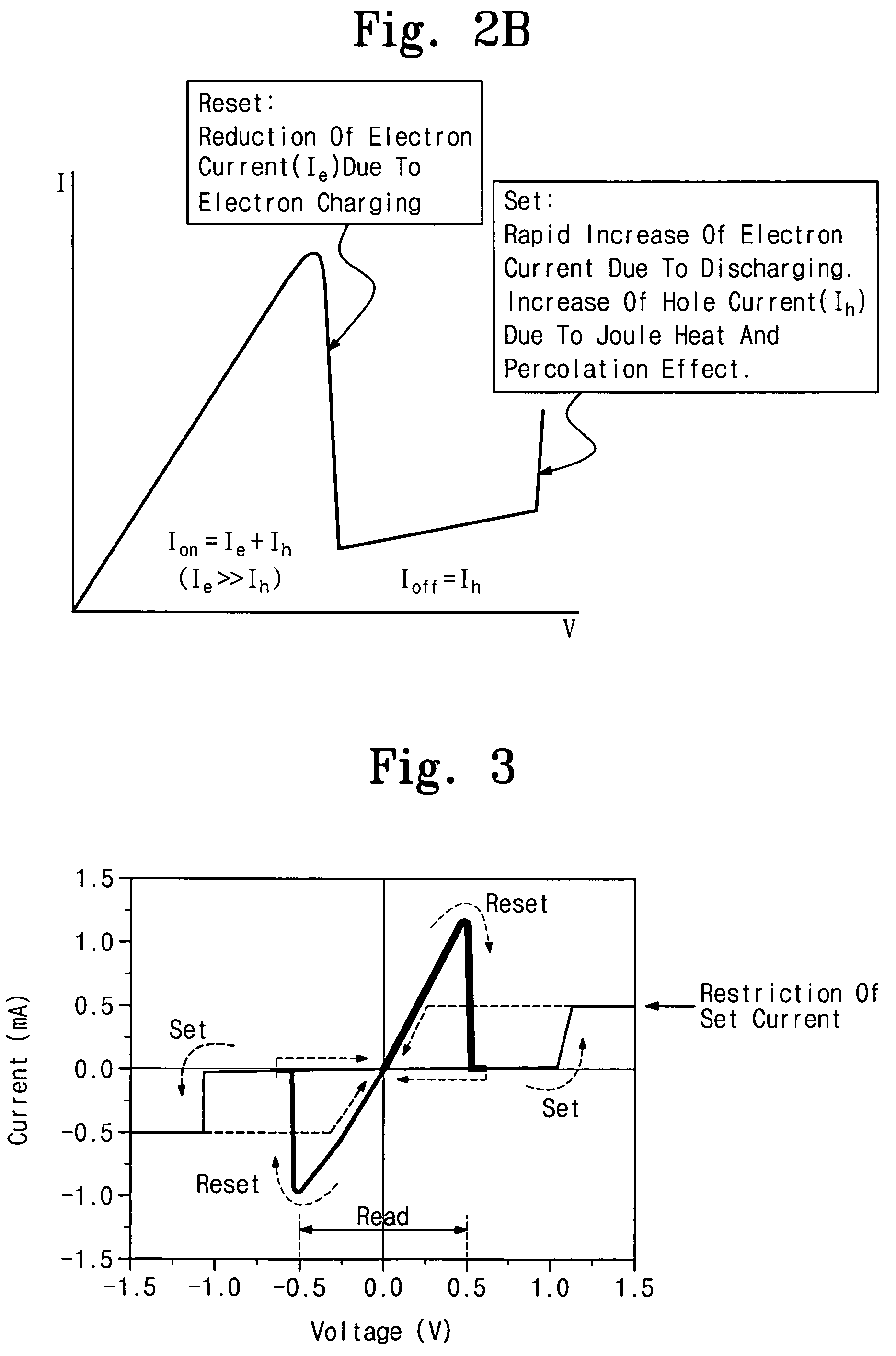
SAMSUNG ELECTRONICS CO LTD
View PDF16 Cites 61 Cited by
  • Summary
  • Abstract
  • Description
  • Claims
  • Application Information

AI Technical Summary

Benefits of technology

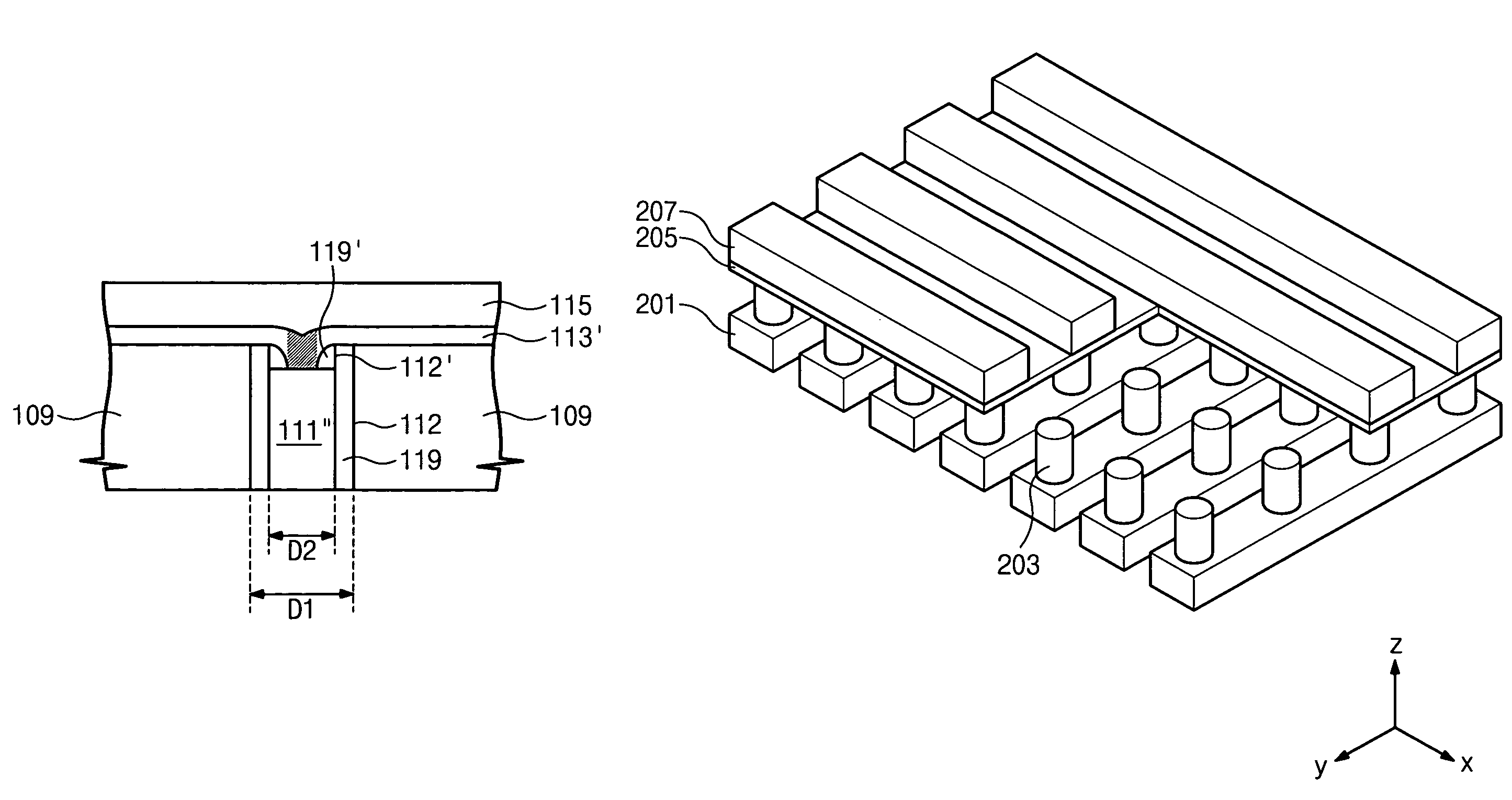
[0015]Some embodiments of the present invention may provide resistive memory cells capable of reducing an overlapping area or contact area between a resistive memory element thin film and an electrode. A resistive memory cell may include a resistive memory element thin film and two electrodes (first electrode and second electrode) connected to both sides of the resistive memory element thin film. One (e.g., the first electrode) of the two electrodes may be configured to be a plug (e.g., first electrode plug) so as to reduce the contact area between the electrode and the resistive memory element thin film, For example, the first electrode may be defined within a contact hole formed in an insulating layer. The first electrode plug can be easily formed using general semiconductor fabricating processes, such as a contact hole process, a conductive material depositing process, an a planarization process.
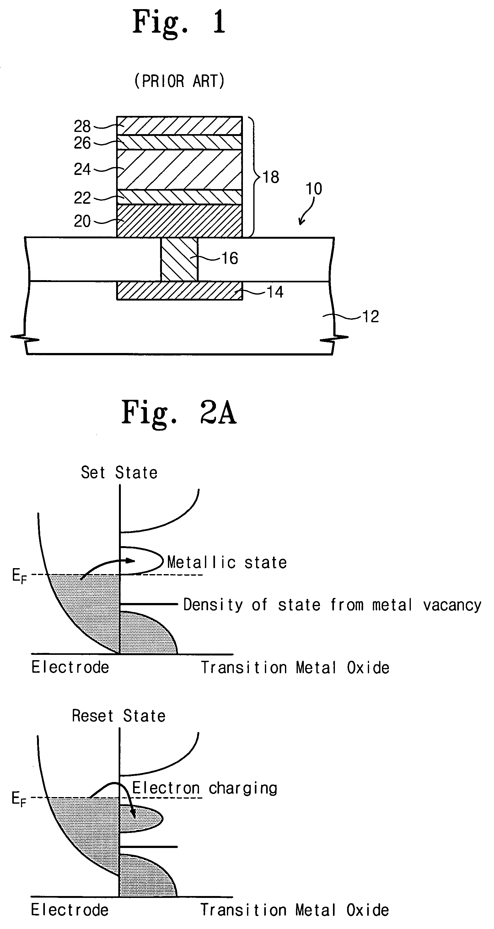
[0017]A resistive memory cell according to some embodiments of the present invention may exhibit good switching operation characteristic because the overlapping area between the electrode and the resistive memory element thin film is reduced. In addition, unlike the prior art as shown in FIG. 1, the first electrode plug may be restricted within the contact hole. Therefore, because photolithography for the first electrode may not be required, it may be advantageous to the implementation of highly integrated memory devices.

Problems solved by technology

In addition, it is known that heat resistant metal, which may be used for the bottom electrode 22, may be difficult to etch.
However, this increased distance between neighboring memory cells may serve as an obstacle to the implementation of a highly integrated memory device.

Method used


Image

  • Resistive memory cells and devices having asymmetrical contacts
  • Resistive memory cells and devices having asymmetrical contacts
  • Resistive memory cells and devices having asymmetrical contacts

Examples


Embodiment Construction

[0053]The present invention will be described more fully hereinafter with reference to the accompanying drawings, in which embodiments of the invention are shown. However, this invention should not be construed as limited to the embodiments set forth herein. Rather, these embodiments are provided so that this disclosure will be thorough and complete, and will fully convey the scope of the invention to those skilled in the art. In the drawings, the thickness of layers and regions are exaggerated for clarity. Like numbers refer to like elements throughout. As used herein the term “and / or” includes any and all combinations of one or more of the associated listed items.

[0054]The terminology used herein is for the purpose of describing particular embodiments and is not intended to be limiting of the invention. As used herein, the singular forms “a”, “an” and “the” are intended to include the plural forms as well, unless the context clearly indicates otherwise. It will be further understo...


PUM


Abstract

A memory cell includes a plug-type first electrode in a substrate, a magneto-resistive memory element disposed on the first electrode, and a second electrode disposed on the magneto-resistive memory element opposite the first electrode. The second electrode has an area of overlap with the magneto-resistive memory element that is greater than an area of overlap of the first electrode and the magneto-resistive memory element. The first surface may, for example, be substantially circular and have a diameter less than a minimum planar dimension (e.g., width) of the second surface. The magneto-resistive memory element may include a colossal magneto-resistive material, such as an insulating material with a perovskite phase and / or a transition metal oxide.

Description

CROSS-REFERENCE TO RELATED APPLICATION[0001]This application claims the benefit of Korean Patent Application No. 2005-25561, filed Mar. 28, 2005, the disclosure of which is hereby incorporated herein by reference in its entirety.BACKGROUND OF THE INVENTION[0002]The present invention relates to memory devices and, more particularly, to magneto-resistive memory devices and methods of fabricating the same.[0003]A resistive memory cell is a nonvolatile memory cell containing a resistive memory element that can reversibly switch between two different resistance states responsive to applied voltage. Colossal magneto-resistive material (CMR) is widely used as a resistive memory element. A resistive memory cell using a CMR element is disclosed in U.S. Pat. No. 6,849,891. The resistive memory cell disclosed in the U.S. Pat. No. 6,849,891 is illustrated in FIG. 1.[0004]Referring to FIG. 1, a conventional magneto-resistive memory cell 18 includes a CMR layer 24, a bottom electrode 20, 22 conta...

Claims


Application Information

Patent Timeline
Patent Type & Authority Patents(United States)
IPC IPC(8): G11C11/00
CPCG11C11/16H01L27/2472H01L45/1233H01L45/04H01L45/147H01L27/2409H01L27/2436H01L27/2481H01L45/146G11C13/0007G11C2213/52G11C11/1659G11C11/161H10B63/82H10B63/84H10B63/20H10B63/30H10N70/20H10N70/8836H10N70/8833H10N70/826
Inventor BAEK, IN-GYULEE, MOON-SOOKKIM, DONG-CHUL
Owner SAMSUNG ELECTRONICS CO LTD
Why Eureka
Try Eureka