
High speed multiple loop DSL system

a multi-loop, high-speed technology, applied in the field of high-speed multiple-loop dsl system and dsl system, can solve the problems of high data rate, achieve the effect of increasing the speed and data carrying capacity of channels, efficient data transmission, and increasing the data carrying capacity of one or mor

Active Publication Date: 2009-12-29
ASSIA SPE LLC CO THE CORP TRUST CO
View PDF50 Cites 82 Cited by
  • Summary
  • Abstract
  • Description
  • Claims
  • Application Information

AI Technical Summary

Benefits of technology

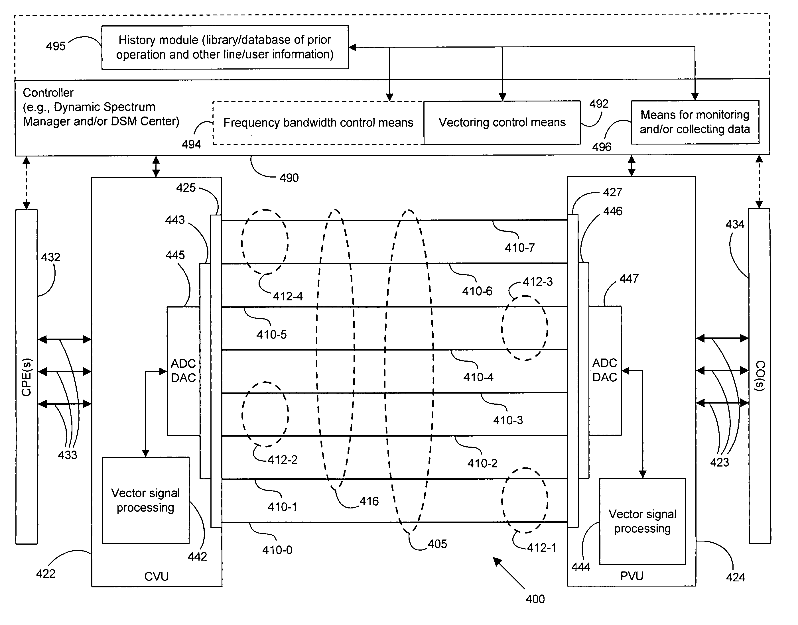
[0011]Signal vectoring is used to increase the speed and data carrying capability of the channels. In some embodiments, an expanded frequency spectrum also can be used to increase the data carrying capability of one or more of the channels. An impedance matching circuit may be coupled to each end of the segment to provided efficient transmission of data across the segment.

Problems solved by technology

Higher data rates are generally prohibited due to the line attenuation, but on short loops are particularly limited by the maximum bandwidth used by the ADSL and VDSL modems and by frequency selective noises caused by crosstalk from other phone lines sharing the same cable, radio ingress, and a variety of customer-premises noises often known generically as impulse noise.

Method used


Image

  • High speed multiple loop DSL system
  • High speed multiple loop DSL system
  • High speed multiple loop DSL system

Examples


Embodiment Construction

[0026]The following detailed description of the invention will refer to one or more embodiments of the invention, but is not limited to such embodiments. Rather, the detailed description is intended only to be illustrative. Those skilled in the art will readily appreciate that the detailed description given herein with respect to the Figures is provided for explanatory purposes as the invention extends beyond these limited illustrative and exemplary embodiments.

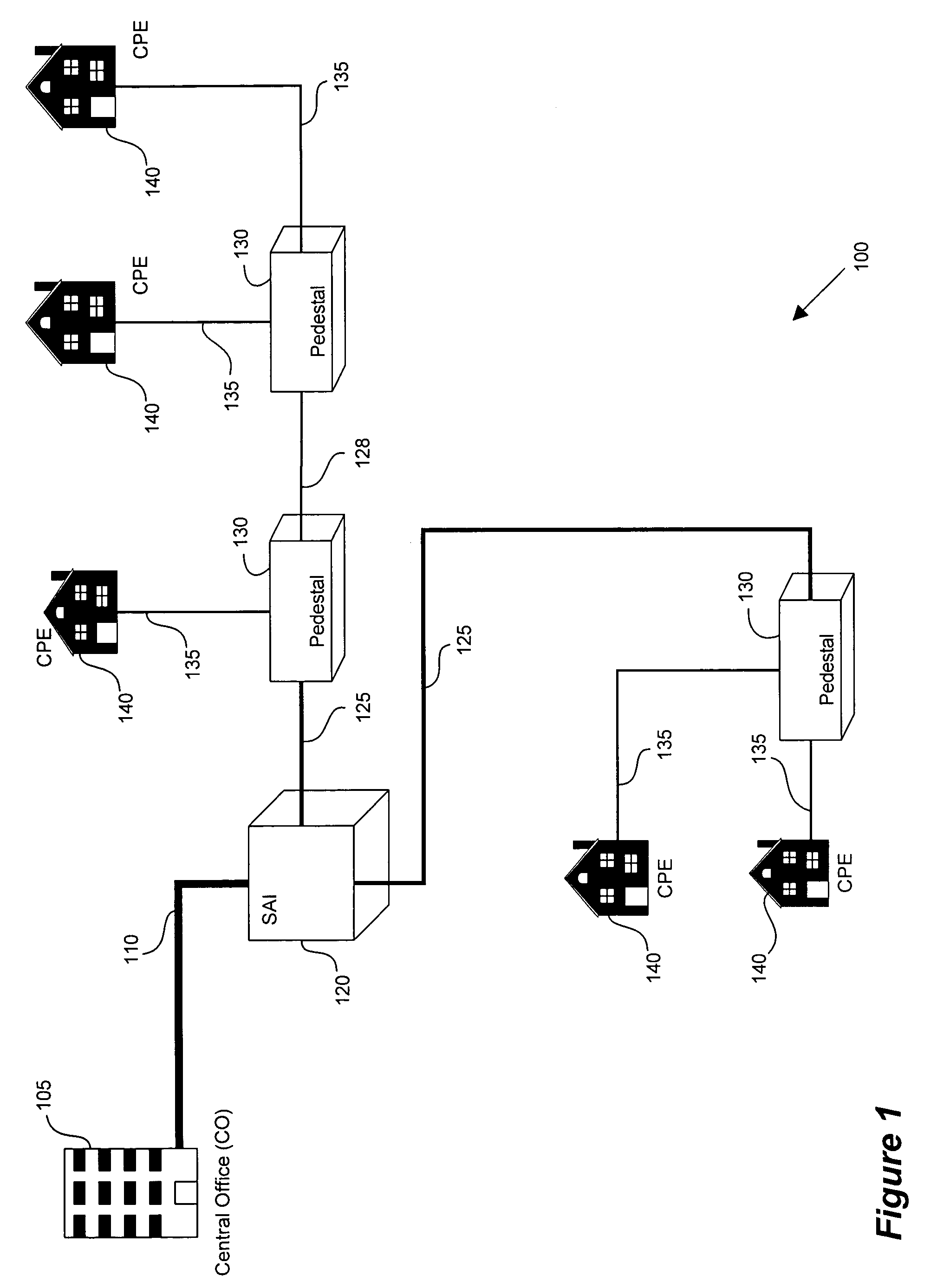
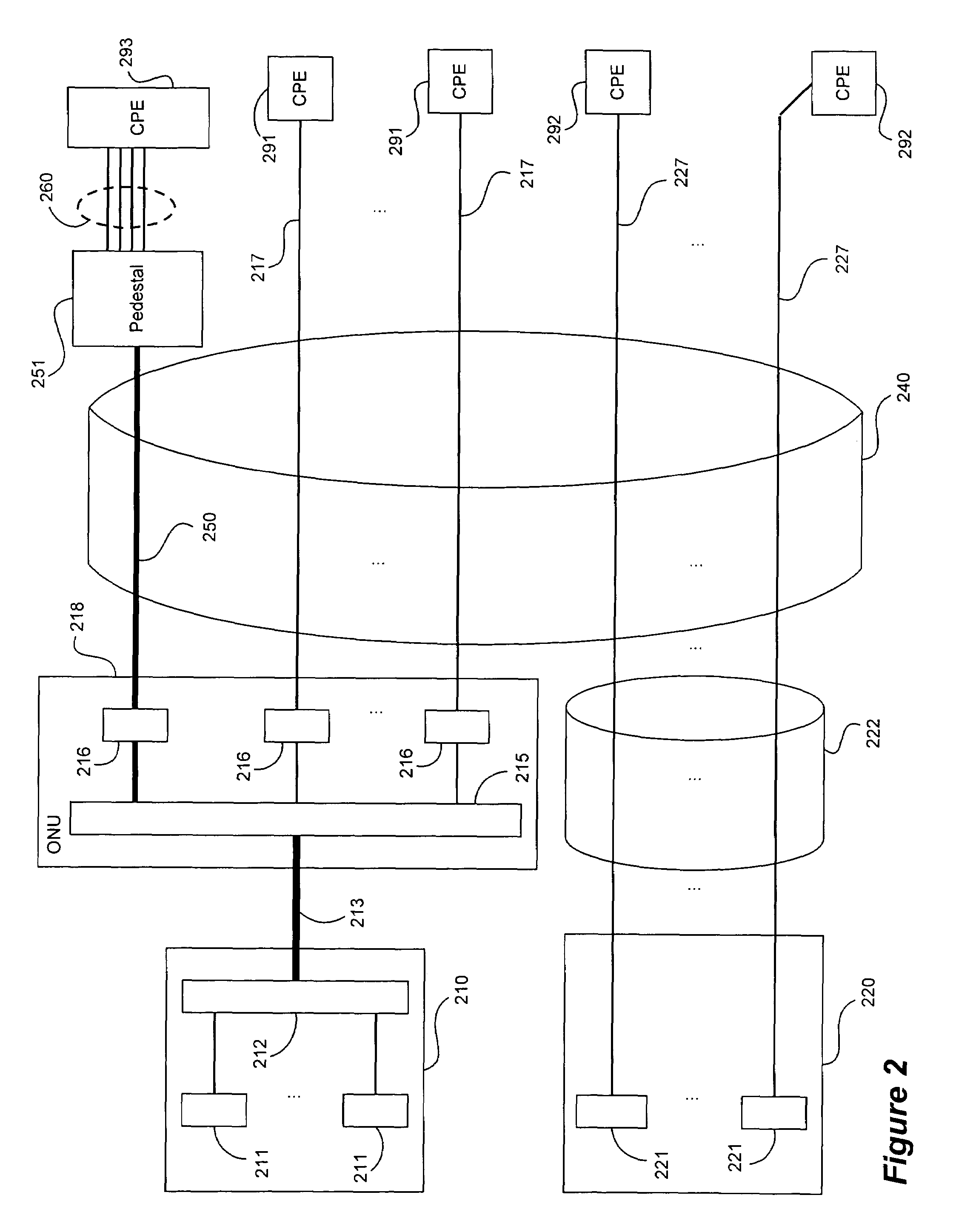
[0027]The present invention leverages the use of multiple loops in a DSL system where the loops can be bonded and are short (though the present invention is not limited solely to short loops). Bonding the loops and vectoring the data transmission on the loops allows the creation and operation of a multiple channel system that typically can achieve data rates greater than the sum of the individual loops' data rates when operated as individual DSL loops.

[0028]The term subscriber loop or “loop” refers to the loop that is formed ...


PUM


Abstract

A DSL system includes a multiple loop segment where K loops are bonded to provide a multiple loop segment having up to (2K−1) communication channels on which transmissions are vectored. The segment may be a drop to a customer premises, an inter-pedestal link, or any other suitable part of a larger DSL system. Generally the bonded loops are relatively short, being 300 meters or less. Signal vectoring is used to increase the speed and data carrying capability of the channels. In some embodiments, an expanded frequency spectrum also can be used to increase the data carrying capability of one or more of the channels. An impedance matching circuit may be coupled to each end of the segment to provided efficient transmission of data across the segment. A controller may provide control signals used to operate the segment as a vectored system and, if desired, frequency bandwidth control signals. The controller may monitor and / or collect data and information from the DSL system to assist in generating control signals. The controller can be a dynamic spectrum manager or DSM Center that includes a computer system and / or other hardware to assist in performing the required functions.

Description

CROSS-REFERENCE TO RELATED APPLICATIONS[0001]This application claims the benefit of priority under 35 U.S.C. § 119(e) of U.S. Provisional No. 60 / 527,853 filed on Dec. 7, 2003, entitled DYNAMIC MANAGEMENT OF COMMUNICATION SYSTEM, the disclosure of which is incorporated herein by reference in its entirety for all purposes.STATEMENT REGARDING FEDERALLY SPONSORED RESEARCH OR DEVELOPMENT[0002]Not applicable.REFERENCE TO SEQUENCE LISTING, A TABLE, OR A COMPUTER PROGRAM LISTING COMPACT DISK APPENDIX[0003]Not applicable.BACKGROUND OF THE INVENTION[0004]1. Field of the Invention[0005]This invention relates generally to methods, systems and apparatus for managing digital communications systems. More specifically, this invention relates to a DSL system using multiple loops in a coordinated manner to provide high speed communications.[0006]2. Description of Related Art[0007]Digital subscriber line (DSL) technologies provide potentially large bandwidth for digital communication over existing tel...

Claims


Application Information

Patent Timeline
Patent Type & Authority Patents(United States)
IPC IPC(8): H04J1/12G06FH04B3/32H04B3/48H04L1/00H04L12/24H04L12/26H04L12/28H04L12/64H04L25/02H04L27/26H04M1/24H04M3/30H04M11/06
CPCH04B3/32H04B3/487H04L1/0019H04L12/26H04L12/2859H04L12/2874H04L12/2898H04L12/6418H04L25/0272H04L25/0278H04L27/2608H04L41/0806H04L41/0853H04L41/142H04L43/00H04L43/0829H04L43/0894H04L43/16H04M3/304H04M11/062H04L1/0002H04L12/2856H04L27/2601H04L43/0847H04L43/0888H04L43/106H04L2012/6478H04M3/2209H04M3/30H04M3/34H01L2924/3011H01L2924/3025H01L2224/45147H01L2224/49175H01L2224/48137H01L2924/00H01L2924/00011H04L5/0044H01L2924/01004
Inventor CIOFFI, JOHN M.
Owner ASSIA SPE LLC CO THE CORP TRUST CO
Learn More