
Method for performing inter-system handovers in a mobile communication system

a mobile communication system and inter-system technology, applied in the field of handovers in mobile communication systems, can solve the problems of requiring the use of conference bridges, unable to meet the needs of mobile terminals, so as to achieve uniform handover procedures

Inactive Publication Date: 2009-12-29
RPX CORP
View PDF10 Cites 41 Cited by
  • Summary
  • Abstract
  • Description
  • Claims
  • Application Information

AI Technical Summary

Benefits of technology

[0039]The benefits of the invention are related to the uniform handling of handover procedures from the mobile terminal software perspective. The invention introduces a mechanism to support a handover from the WLAN radio access to a licensed band radio access. The invention avoids the introduction of extra hardware components to the core network for the handling of voice or multimedia bearers in the case of handover. The invention also enables the easy incorporation of MSC servers and RNCs to the handling of a call originally established by IMS.

Problems solved by technology

This is due to the fact that WLANs offer a much more limited and patched radio coverage, which is usually even overlapping with the radio access provided by the cellular communication system.
The problem associated with the mentioned solution for handovers is that it requires the use of a conference bridge.
A further disadvantage is the implementation of handover procedures in mobile terminal side, which deviate from the normal intra-cellular communication system handover procedures.
The mobile terminal is not able to reuse the software for the implementing of intra-cellular communication system handovers in the implementing of inter-system handovers.

Method used


Image

  • Method for performing inter-system handovers in a mobile communication system
  • Method for performing inter-system handovers in a mobile communication system
  • Method for performing inter-system handovers in a mobile communication system

Examples


Embodiment Construction

[0052]Reference will now be made in detail to the embodiments of the present invention, examples of which are illustrated in the accompanying drawings.

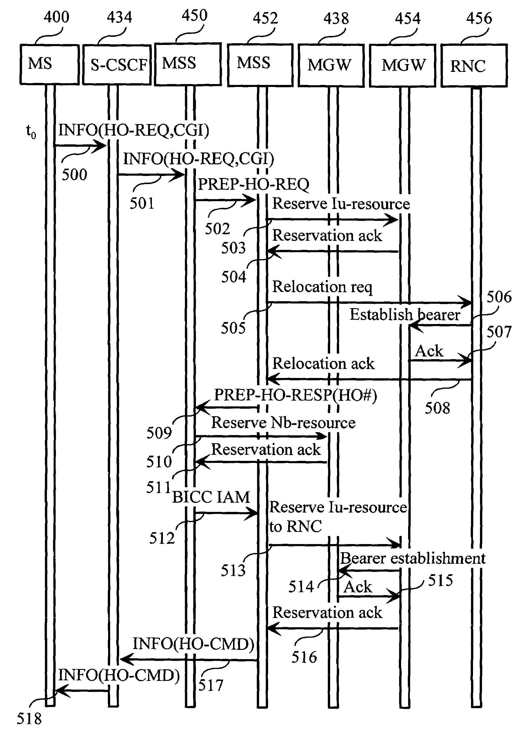
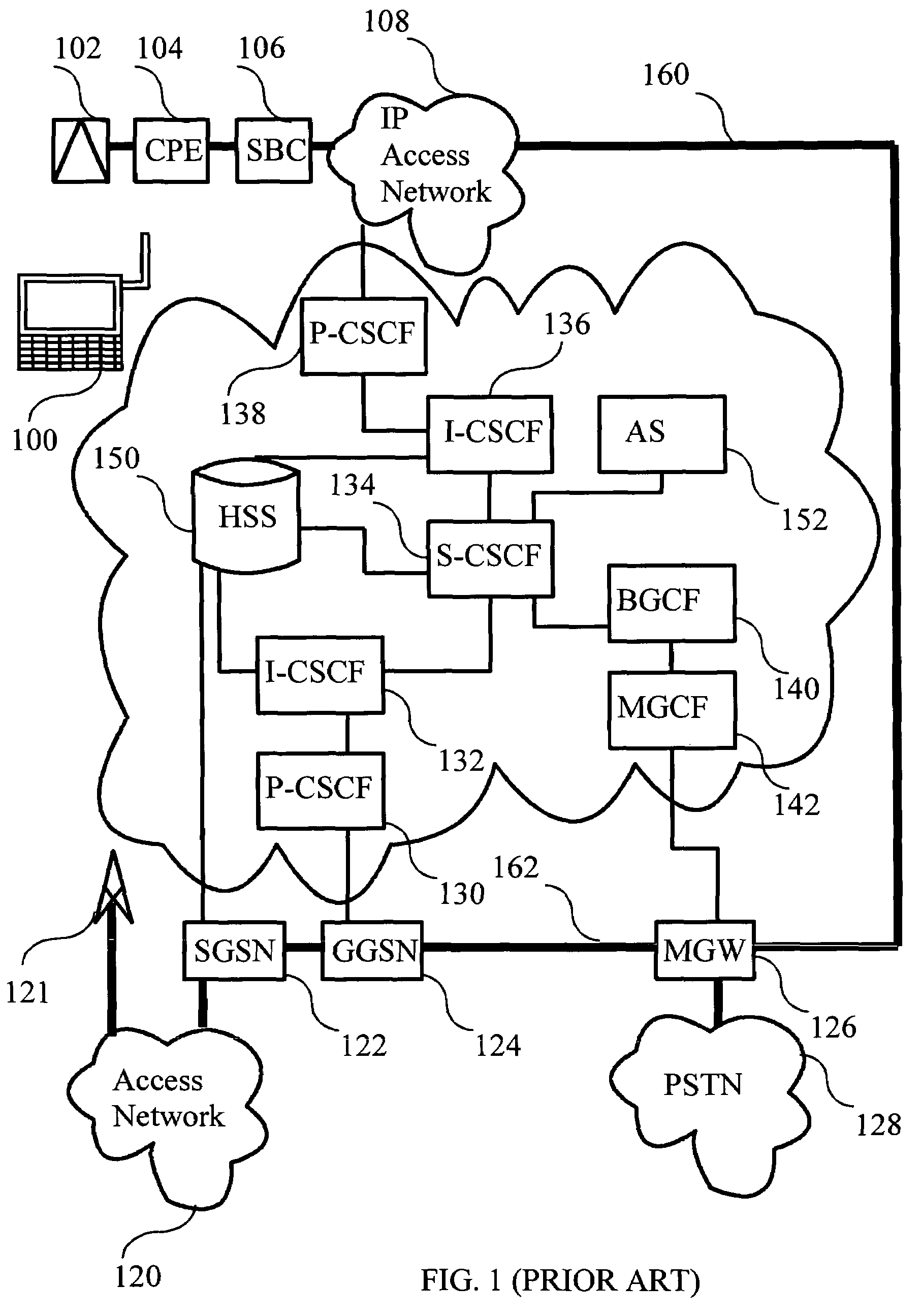
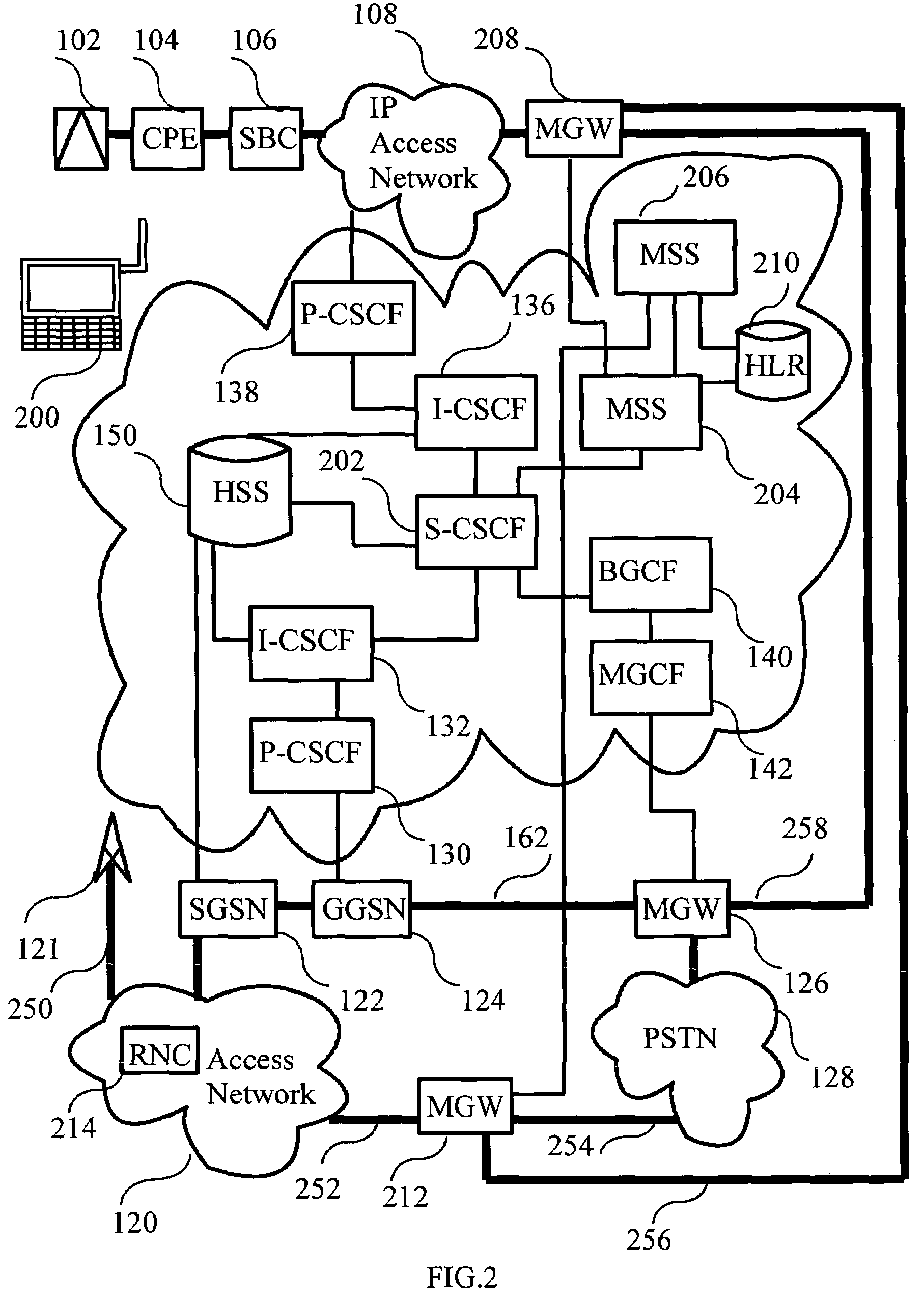
[0053]FIG. 2 is a block diagram illustrating an IP Multimedia Subsystem (IMS), a 2G / 3G IP Connectivity Access Network (IP-CAN) and an unlicensed band IP Connectivity Access Network (IP-CAN) according to the invention. In FIG. 2 there is a dual system mobile station 200, which is capable of communicating using both unlicensed band radio access and licensed band radio access. Mobile station 200 is configured with capability to perform handover from unlicensed band radio access to licensed band radio access. In addition to the IP Multimedia Subsystem (IMS) network elements introduced in FIG. 1 there is a first Mobile Switching Center (MSC) Server (MSS) 204 and a second mobile switching center server 206 and a home location register 210, which communicates with the mentioned mobile switching center servers and stores subscriber data assoc...


PUM


Abstract

The invention relates to a method for performing inter-system handovers in a communication system comprising at least a mobile station, a call state control function, a first and a second call control node, a first and a second media gateway and a radio network node. The handover is achieved by way of connecting a call control node to a call state control function. The call control node allocates a media gateway for the session established. The session media bearers are routed via the media gateway. The call control node acts as an anchor node for the handover. As the mobile station moves to a new cell a media bearer is established to the media gateway from the mobile station via the new cell.

Description

BACKGROUND OF THE INVENTION[0001]1. Field of the Invention[0002]The invention relates to handovers in mobile communication systems. Particularly, the invention relates to a method for performing handover between a Wireless Local Area Network (WLAN) and a licensed band cellular communication system.[0003]2. Description of the Related Art[0004]Recently Wireless Local Area Networks (WLAN) have become important in mobile communications. The advantage of WLANs over licensed band cellular communication systems such as the Universal Mobile Telecommunication system (UMTS) and Global System of Mobile communications (GSM) lies in the facts that they use an unlicensed band and the cell sizes are much smaller. Hereinafter, the term cellular communication system refers to a communication system operating in the licensed band. These facts make possible to build private WLANs operated by small corporate entities and individual users. The cost of wireless communication in these WLANs is significant...

Claims


Application Information

Patent Timeline
Patent Type & Authority Patents(United States)
IPC IPC(8): H04M1/00H04W36/00H04L12/28H04L12/56H04W36/14H04W72/04H04W76/02H04W76/06H04W80/00H04W80/10H04W88/06H04W88/16
CPCH04W36/0066H04L65/1043H04W72/04H04W76/02H04W76/06H04W80/10H04W88/06H04W88/16H04L65/1016H04W80/00H04W76/30H04W76/10H04L65/1095
Inventor KALLIO, JUHA
Owner RPX CORP
Learn More