Engineering method and system for industrial automation systems

a technology of industrial automation and engineering system, applied in the direction of computer control, program control, instruments, etc., can solve the problems of extremely long compilation or generation run time, and achieve the effect of facilitating handling, increasing the agility of a company, and easy chang

Inactive Publication Date: 2010-02-02
SIEMENS AG
View PDF13 Cites 16 Cited by
  • Summary
  • Abstract
  • Description
  • Claims
  • Application Information

AI Technical Summary

Benefits of technology

[0008]According to the invention the aforementioned object is achieved by the claims. The meta information associated with an object describes, for example, which data and functions an object contains, but meta information can also contain descriptions relating to implementation and operation or include user documentation, or information about the overall process, the business process or the production process. In markup languages such as HTML or XML, meta information can be described by way of so-called tags or by way of attributes and be assigned to the objects. Meta information can also be provided with a hierarchical structure. One advantage of the invention consists in the fact that no explicit code generation is required in order to allow an installation specification created in the engineering phase to run. The processing logic and the process sequence of the installation represented by the tree are defined from the structure of the tree and its networked connections. The structure of the tree, which can be modified manually or automatically at runtime, and the networked connections of the tree elements determine which operands are supplied to functions and whether functions are executed sequentially or in parallel. With regard to industrial installations, the structure of the tree and the networked connections of the tree elements serve to determine, for example, which input variables are supplied to devices and how the output values generated by the device are further processed. The tree and the networked connections are edited graphically by a user on an engineering system. The form of representation for the trees can be different and can be freely chosen by the user. The networked connections or cross-referencing by means of pointers of the tree elements can be effected by the hierarchical arrangement in the tree. However, networked connections or cross-referencing by means of pointers of the tree elements can also be made by means of references edited by the user or lateral networked connections to elements in other sub-trees. The inputs for creating the tree and for establishing networked connections can be made by way of input masks, drag & drop mechanisms or by using voice input.
[0009]The implementation of the objects, in other words their code and meta information, is associated with the individual objects. As a result of the fact that the application created in the engineering phase is composed at runtime of prefabricated objects (for example, automatically on the basis of their meta information), it is possible to dispense with an explicit compilation phase for generating the code of the application to be produced by the engineering phase. Compilation or generation runs can last an extremely long time. As a result of the fact that explicit compilation runs or generation runs are not required because the runtime system is always directly modified incrementally, the time needed to create the installation specification, perform testing and commissioning is kept to a minimum.
[0010]A further important advantage consists in the fact that programs and data are handled in a uniform manner. Data are object trees without functions, programs are object trees with functions. All the mechanisms present in a runtime system for combining, interconnecting, versioning, saving, transporting etc. data and programs only need to be implemented once and not separately for data and for programs. This also facilitates handling for software developers, commissioning engineers and administrators since they only need to familiarize themselves once with these mechanisms.
[0011]A further advantage consists in the fact that changes can be made very easily. Sub-trees can be added, modified or removed at any time without the need to modify the entire tree structure. This increases the agility of a company because it can react more quickly to changed market needs. This is important particularly when the applications created during the engineering phase are used for controlling automation systems, production installations or MES systems.
[0012]The networking, cross-referencing by means of pointers or referencing between the objects can happen at differing levels of granularity. A networked connection can thus be effected for example by reference to physical addresses (by using cursors or pointers), as a result of which a high level of efficiency (for example within the execution of a process) is achieved. Other networking mechanisms are for example electronic messages (email for example), telephone or fax. An appropriate networking mechanism can be chosen by the user depending on the requirements of the underlying application.
[0013]Existing installations or automation systems are characterized by a high level of complexity. The complexity, which is responsible for the rise in the durability costs, lies both in the individual installation (devices for example) and / or automation components (actuators and sensors for example) and also in the interaction of the components in providing an overall solution. If the know-how concerning the interaction of the components is linked by meta information to the components or objects, it is possible thereby to gain a significant competitive advantage since the durability costs of the automation and installation components can be reduced as a result. The presence of meta information at and / or in the objects offers automatic support for personnel up to and including automatic implementation of the following functions: commissioning, operation, maintenance, modification or repair.

Problems solved by technology

Compilation or generation runs can last an extremely long time.

Method used


Image

  • Engineering method and system for industrial automation systems
  • Engineering method and system for industrial automation systems
  • Engineering method and system for industrial automation systems

Examples


Embodiment Construction

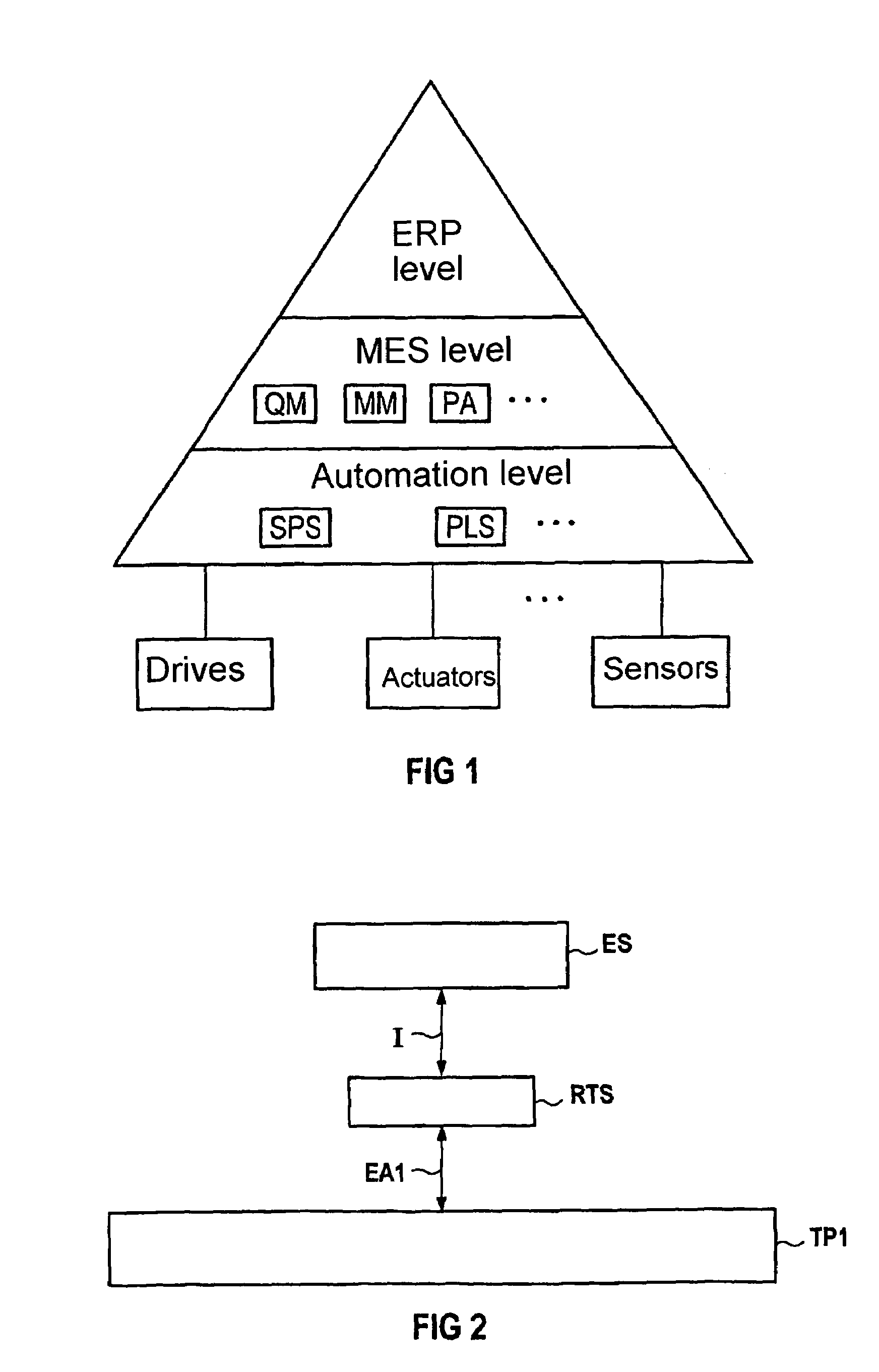
[0057]The representation shown in FIG. 1 illustrates in a basic block diagram the three control levels as they are normally to be found in a production and / or manufacturing company. The pyramidal form is indicative of the fact that a compression of information takes place towards the top. The uppermost level is the ERP level (Enterprise Resource Planning). The business administration and sales / marketing functions are normally performed on this company management level in a company (for example financial system, sales and marketing, personnel, reporting). However, logistical tasks which span more than one production installation (order and materials management, for example) are also performed on this level. The SAP R / 3 system is an ERP system which is used very frequently on the company management level.

[0058]The lowermost level of the pyramid is the automation level (controls). Programmable controllers (SPS) in conjunction with visualization and process control systems (PLS) are nor...


PUM


Abstract

The invention relates to an engineering method and system for industrial automation systems, in particular for MES systems, based on at least one computational unit with an input auxiliary device, an output auxiliary device, in addition to at least one display device. According to said method, the modelled objects comprise installation structures or installation parts and are linked to meta information. The modelled objects are structured in the engineering method as hierarchical trees and can be interconnected by lateral networking or by means of a cursor. The objects are executed in run-time by evaluating the meta information in a target system, whereby the functions of an installation that has been modelled in the engineering method are determined from the structure of the tree and the networked connections.

Description

CROSS REFERENCE TO RELATED APPLICATIONS[0001]This application is the US National Stage of International Application No. PCT / DE03 / 00358, filed Feb. 7, 2003 and claims the benefit thereof. The International Application claims the benefits of German application No. 10206902.6 filed Feb. 19, 2002, both of the applications are incorporated by reference herein in their entirety.FIELD OF INVENTION[0002]The invention relates to an engineering method and an engineering system for industrial automation systems, in particular for MES systems, based on at least one computational unit with an input auxiliary device, an output auxiliary device, and also at least one display device.[0003]In addition, the invention relates to a computer program, a data medium and a data processing facility.BACKGROUND OF INVENTION[0004]The use of so-called manufacturing execution systems (MES) for the automation of production or manufacturing processes is known from “Software für die Automatisierung—Transparenz über...

Claims


Application Information

Patent Timeline
Patent Type & Authority Patents(United States)
IPC IPC(8): G06F17/50G06F19/00G06G7/48G05B19/042G06Q10/00
CPCG05B19/0426G06Q10/06G05B2219/23292G05B2219/36121
Inventor THURNER, ELMAR
Owner SIEMENS AG
Why Eureka
Try Eureka