Arrangements and methods for abrasive flow machining

Inactive Publication Date: 2016-03-24
UNIVERSITY OF LJUBLJANA
View PDF5 Cites 17 Cited by
  • Summary
  • Abstract
  • Description
  • Claims
  • Application Information

AI Technical Summary

Benefits of technology

[0009]The present invention fulfils this need by providing methods, and corresponding apparatuses, for abrasive flow machining, in which methods an abrasive medium is extruded through a passage, and in which deflection objects are inserted into the passageway, preferably in the passages, or sections thereof, having relatively large cross-sectional area. The deflection elements effect a local reduction of the effective cross sectional area available for fluid flow. Hence, they increase the velocity of the abrasive medium lo

Problems solved by technology

While the conventional abrasive flow machining processes are effective in many applications, the conventional processes are often in ineffective, in particular, when the surface to be treated is an interior surface of a passage, which passage is either very long and narrow, or in cases where the passage comprises multiple sections having cross-sectional areas of different magni

Method used


Image

  • Arrangements and methods for abrasive flow machining
  • Arrangements and methods for abrasive flow machining
  • Arrangements and methods for abrasive flow machining

Examples


first embodiment

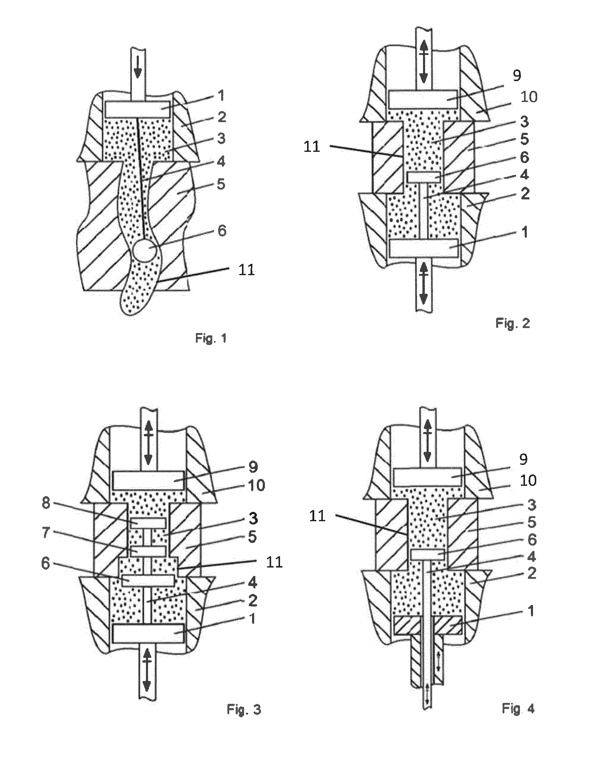
[0063]FIG. 1 shows the invention. Shown is an arrangement for the treatment of an interior surface of a workpiece 5. A cylinder portion 2 and a piston 1 form a first chamber. The first chamber holds and abrasive medium 3. Connected to piston 1 is a rod 4 on which a deflection object 6 is mounted. Deflection object 6, in this embodiment, has spherical shape. Rod 4 keeps deflection object 6 at a fixed distance from piston 1. The first chamber is connected in a fluid-tight manner to workpiece 5. As shown by an arrow on piston 1, the piston is movable downwardly in the vertical direction, so as to impose an increased pressure on abrasive fluid 3 in the first chamber. When piston 1 moves downwardly the first chamber, abrasive fluid 3 is pressed (or extruded) through the internal passage 11 of workpiece 5. In the embodiment shown in FIG. 1, interior passage 11 has an inlet portion at its upper end and an outlet portion at its lower end. The embodiment does not include second chamber conne...

second embodiment

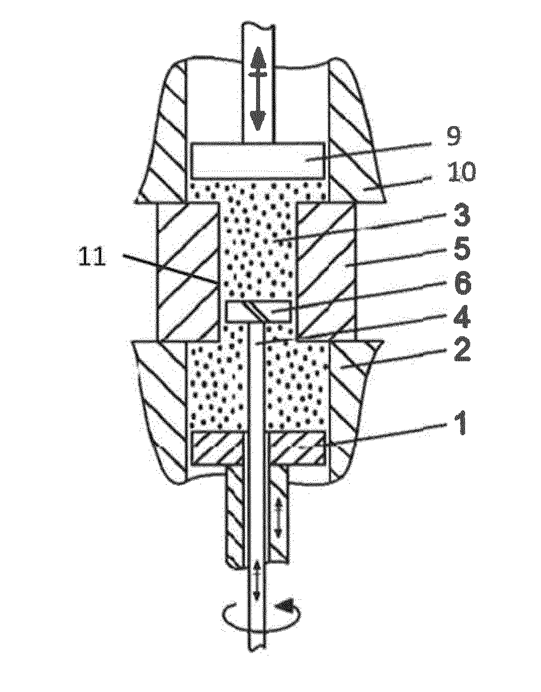
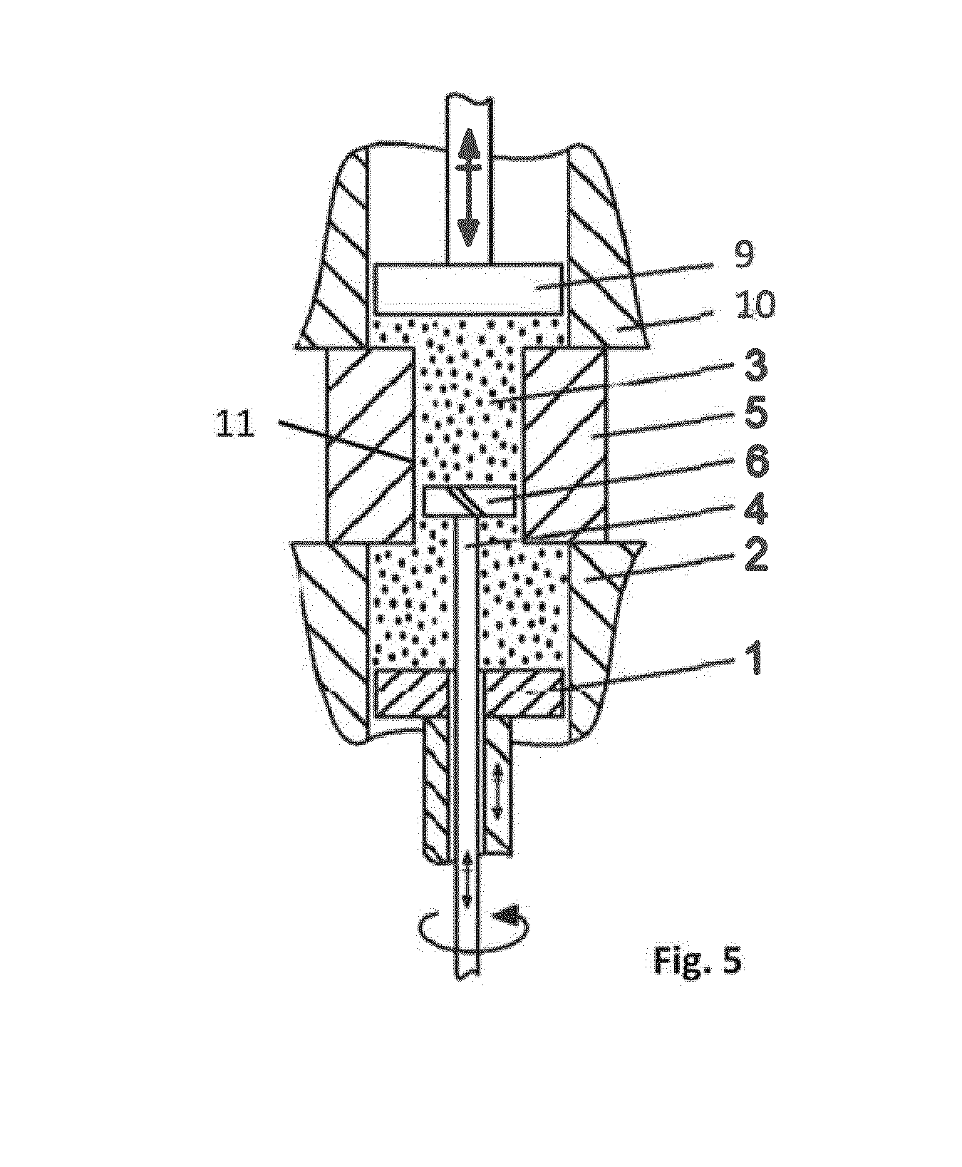
[0064]FIG. 2 depicts the invention. In this embodiment, a first chamber is formed from cylindrical portion 2 and corresponding piston 1. The first chamber is filled with abrasive fluid 3. Piston 1 is movable in a vertical direction, in this case to perform a reciprocating movement. Connected to piston 1 is rod 4 to which deflecting object 6 is connected. Movement of piston 1 effects movement of rod 4 and deflecting object 6 at the same speed and frequency. When piston 1 moves upwardly, abrasive fluid 3 is forced into the interior passage, past the moving deflecting object 6, into a second chamber, in this case formed by second cylindrical portion 10 and second piston 9. As will be readily appreciated by the person skilled in the art, the velocity of abrasive fluid 3 in interior passage 11 is increased around the deflecting object 6, relative to the velocity in the remainder of interior passage 11, because around the deflecting object the available for cross-sectional area for fluid ...

third embodiment

[0065]FIG. 3 shows the invention. This embodiment includes first and second fluid chambers, formed by cylindrical portions 2 and 10 with corresponding pistons 1 and 9, respectively. Reciprocal motion of first and second pistons 1 and 9 effects a reciprocal flow of abrasive medium 3 through the interior passage 11. As can be seen from the Figure, interior passage 11 has sections of different cross-sectional area. A first section, vertically below a second section, has a larger cross-sectional area than has the second section. In conventional abrasive fluid machining arrangements, this would lead to a less effective machining of the surface in the first section having the larger cross-sectional area. According to the invention, however, multiple deflecting objects 6, 7, 8 may be provided in interior passage 11, thereby effecting a substantially uniform treatment of the surfaces of first and second sections. In the embodiment shown in FIG. 3, three separate deflecting objects 6, 7, 8 a...


PUM

PropertyMeasurementUnit
Pressureaaaaaaaaaa
Flow rateaaaaaaaaaa
Structureaaaaaaaaaa

Abstract

A method of treating an interior surface of a workpiece (5); said method comprising providing a workpiece (5) having an interior passage (11) defined at least partly by said interior surface to be treated, said passage (11) having an inlet section and an outlet section; providing in said interior passage (11) at least one deflecting object (6), said deflecting object (6) having an outer surface, whereby a space is formed between said outer surface of said at least one deflecting object (6) and said interior surface of said workpiece (5); providing an abrasive fluid (3) in said space, such that said space is substantially filled with said abrasive fluid (3); and effecting flow of said abrasive medium (3) through said interior passage (11) from said inlet portion to said outlet portion.

Description

FIELD OF THE INVENTION[0001]The present invention is in the field of abrasive flow machining More specifically, the present invention relates to new and improved arrangements and methods for treating interior surfaces of workpieces with abrasive fluids.BACKGROUND OF THE INVENTION[0002]Abrasive flow machining is a well-known machining process, in which an abrasive medium is extruded through, or past, a workpiece surface, to effect an abrasive surface treatment of the same. The abrasive action in abrasive flow machining may be seen as being analogous to conventional filing, grinding, lapping or honing, in that the extruded abrasive medium passes by a surface of a workpiece, thereby abrading the material forming the surface and thus treating the surface. If suitable non-Newtonian fluids are used, the abrasive fluid may flow through, or past, a workpiece substantially in plug flow. The plug may then be seen as a self-forming file, grinding stone or lap, as it is extruded under pressure ...

Claims


Application Information

Patent Timeline
IPC IPC(8): B24B31/116
CPCB24B31/116B24B31/006
Inventor KENDA, JANIPUSAVEC, FRANCIKOPAC, JANEZ
Owner UNIVERSITY OF LJUBLJANA
Why Eureka
Try Eureka